Nissan Versa (N17): P0890 TCM
DTC Logic
DTC DETECTION LOGIC
| DTC | Trouble diagnosis name | DTC detection condition | Possible causes |
| P0890 | Transmission control module power relay sense circuit low | The battery voltage supplied to the TCM is
less than 8.4 V continuously for 200 msec or
more under the following diagnosis condition: - Diagnosis condition - TCM power supply voltage: More than 11 V |
Harness or connector (TCM power supply (back-up) circuit is open or shorted.) |
DTC CONFIRMATION PROCEDURE
1.PREPARATION BEFORE WORK
If another "DTC CONFIRMATION PROCEDURE" occurs just before, turn ignition switch OFF and wait for at least 10 seconds, then perform the next test.
>> GO TO 2.
2.CHECK DTC DETECTION
- Start the engine and wait for 5 seconds or more.
- Check the DTC.
Is "P0890" detected?
YES >> Go to TM "Diagnosis Procedure".
NO >> INSPECTION END
Diagnosis Procedure
1.CHECK TCM POWER SUPPLY (BACK-UP) CIRCUIT
- Turn ignition switch OFF.
- Disconnect TCM connector.
- Check voltage between TCM harness connector terminals and ground.
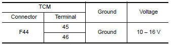
Is the inspection result normal?
YES >> Check intermittent incident. Refer to GI "Intermittent Incident".
NO >> GO TO 2.
2.DETECT MALFUNCTIONING ITEMS
Check the following items:
- Open or short circuit of harness between battery positive terminal and TCM connectors terminals 45 and 46.
- 10A fuse (No.25, fuse and fusible link block). Refer to PG "Terminal Arrangement".
Is the inspection result normal?
YES >> Check intermittent incident. Refer to GI "Intermittent Incident".
NO >> Repair or replace malfunctioning parts.
 P0863 TCM Communication
DTC Logic DTC DETECTION LOGIC DTC Trouble diagnosis name DTC detection condition Possible causes P0863 TCM Communication Circui An error is detected at the initial CA ...

Other materials:
Servicing air conditioner
The air conditioner system in your NISSAN vehicle
is charged with a refrigerant designed with
the environment in mind.
This refrigerant does not harm the earth's
ozone layer.
Special charging equipment and lubricant is required
when servicing your NISSAN air conditioner.
Using improper ...
EVAP control system pressure sensor
Exploded View
1. EVAP control system pressure sensor 2. O-ring 3. EVAP canister
Removal and Installation
NOTE:
The EVAP canister system pressure sensor can be removed without removing the
EVAP canister.
REMOVAL
Remove the EVAP canister protector cover.
Disconnect EVAP canister purg ...
Categories
- Manuals Home
- Nissan Versa Owners Manual
- Nissan Versa Service Manual
- Video Guides
- Questions & Answers
- External Resources
- Latest Updates
- Most Popular
- Sitemap
- Search the site
- Privacy Policy
- Contact Us

0.0058