
Nissan Versa (N17): P0962 Pressure control solenoid A
DTC Logic
DTC DETECTION LOGIC
| DTC | Trouble diagnosis name | DTC detection condition | Possible causes |
| P0962 | Pressure Control Solenoid A Control Circuit Low | The line pressure solenoid valve current is
200 mA or less continuously for 200 msec or
more under the following diagnosis conditions: - Diagnosis conditions - Solenoid output current: 750 mA or more - GND short diagnosis of the solenoid drive circuit is satisfied. - TCM power supply voltage: More than 11 V |
- Harness or connector
(Line pressure solenoid valve circuit is
shorted to ground) - Line pressure solenoid valve |
DTC CONFIRMATION PROCEDURE
1.PREPARATION BEFORE WORK
If another "DTC CONFIRMATION PROCEDURE" occurs just before, turn ignition switch OFF and wait for at least 10 seconds, then perform the next test.
>> GO TO 2.
2.CHECK DTC DETECTION
- Start the engine and wait for 5 seconds or more.
- Check the first trip DTC.
Is "P0962" detected?
YES >> Go to TM "Diagnosis Procedure".
NO >> INSPECTION END
Diagnosis Procedure
1.CHECK CIRCUIT BETWEEN TCM AND CVT UNIT
- Turn ignition switch OFF.
- Disconnect TCM connector and CVT unit connector.
- Check continuity between TCM harness connector terminal and ground.

Is the inspection result normal?
YES >> GO TO 2.
NO >> Repair or replace malfunctioning parts.
2.CHECK LINE PRESSURE SOLENOID VALVE
Check line pressure solenoid valve. Refer to TM, "Component Inspection (Line Pressure Solenoid Valve)".
Is the inspection result normal?
YES >> Check intermittent incident. Refer to GI "Intermittent Incident".
NO >> Repair or replace malfunctioning parts.
Component Inspection (Line Pressure Solenoid Valve)
1.CHECK LINE PRESSURE SOLENOID VALVE
Check resistance between CVT unit connector terminal and ground. 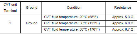
Is the inspection result normal?
YES >> INSPECTION END
NO >> There is a malfunction of line pressure solenoid valve. Replace transaxle assembly. Refer to TM "Removal and Installation".
 P0890 TCM
Other materials:
Input shaft and gear
Exploded View
1. Input shaft front bearing 2. Input shaft 3. Snap ring
4. Input shaft rear bearing 5. Adapter plate 6. Bushing
7. 5th input gear 8. 5th-reverse baulk ring 9. Synchronizer lever
10. 5th-reverse synchronizer hub 11. 5th-reverse coupling sleeve 12. Lock washer
13. Retaining pi ...
Transmission assembly
Exploded View
1. Transaxle assembly
A : For the tightening torque, refer to TM "Removal and Installation".
Removal and Installation
WARNING:
Do not open the radiator cap or drain plug when the engine is hot.
Hot liquid may spray out, causing
serious injury.
Perform the ...
Categories
- Manuals Home
- Nissan Versa Owners Manual
- Nissan Versa Service Manual
- Video Guides
- Questions & Answers
- External Resources
- Latest Updates
- Most Popular
- Sitemap
- Search the site
- Privacy Policy
- Contact Us

0.0085