Nissan Versa (N17): P2135 TP sensor
DTC Logic
DTC DETECTION LOGIC
NOTE: If DTC P2135 is displayed with DTC P0643, first perform the trouble diagnosis for DTC P0643. Refer to EC, "DTC Logic".
| DTC No. | Trouble diagnosis name | DTC detecting condition | Possible cause |
| P2135 | Throttle position sensor circuit range/performance | Rationally incorrect voltage is sent to ECM compared with the signals from TP sensor 1 and TP sensor 2. |
|
DTC CONFIRMATION PROCEDURE
1.PRECONDITIONING
If DTC Confirmation Procedure has been previously conducted, always perform the following before conducting the next test.
- Turn ignition switch OFF and wait at least 10 seconds.
- Turn ignition switch ON.
- Turn ignition switch OFF and wait at least 10 seconds.
TESTING CONDITION: Before performing the following procedure, confirm that battery voltage is more than 10 V at idle.
>> GO TO 2.
2.PERFORM DTC CONFIRMATION PROCEDURE
- Start engine and let it idle for 1 second.
- Check DTC.
Is DTC detected?
YES >> Go to EC, "Diagnosis Procedure".
NO >> INSPECTION END
Diagnosis Procedure
1.CHECK GROUND CONNECTION
- Turn ignition switch OFF.
- Check ground connection E15. Refer to Ground Inspection in GI, "Circuit Inspection".
Is the inspection result normal?
YES >> GO TO 2.
NO >> Repair or replace ground connection.
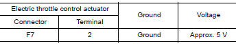
2.CHECK THROTTLE POSITION SENSOR POWER SUPPLY CIRCUIT
- Disconnect electric throttle control actuator harness connector.
- Turn ignition switch ON.
- Check the voltage between electric throttle control actuator harness
connector and ground.
Is the inspection result normal?
YES >> GO TO 3.
NO >> Repair open circuit or short to ground or short to power in harness or connectors.
3.CHECK THROTTLE POSITION SENSOR GROUND CIRCUIT FOR OPEN AND SHORT
- Turn ignition switch OFF.
- Disconnect ECM harness connector.
- Check the continuity between electric throttle control actuator harness
connector and ground.
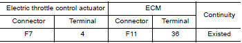
- Also check harness for short to ground and short to power.
Is the inspection result normal?
YES >> GO TO 4.
NO >> Repair open circuit or short to ground or short to power in harness or connectors.
4.CHECK THROTTLE POSITION SENSOR INPUT SIGNAL CIRCUIT FOR OPEN AND SHORT
- Check the continuity between electric throttle control actuator harness
connector and ground.
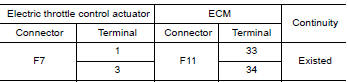
- Also check harness for short to ground and short to power.
Is the inspection result normal?
YES >> GO TO 5.
NO >> Repair open circuit or short to ground or short to power in harness or connectors.
5.CHECK THROTTLE POSITION SENSOR
Refer to EC, "Component Inspection".
Is the inspection result normal?
YES >> GO TO 7.
NO >> GO TO 6.
6.REPLACE ELECTRIC THROTTLE CONTROL ACTUATOR
Replace electric throttle control actuator. Refer to EM, "Removal and Installation".
>> INSPECTION END
7.CHECK INTERMITTENT INCIDENT
Refer to GI, "Intermittent Incident".
>> INSPECTION END
Component Inspection
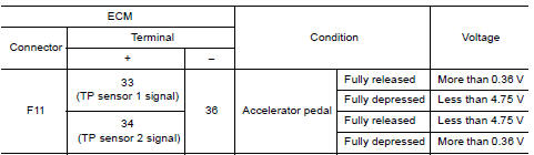
1.CHECK THROTTLE POSITION SENSOR
- Turn ignition switch OFF.
- Reconnect all harness connectors disconnected.
- Perform EC, "Work Procedure".
- Turn ignition switch ON.
- Set selector lever to D (A/T or CVT) or 1st (M/T) position.
- Check the voltage between ECM harness connector and ground.
Is the inspection result normal?
YES >> INSPECTION END
NO >> GO TO 2.
2.REPLACE ELECTRIC THROTTLE CONTROL ACTUATOR
Replace electric throttle control actuator. Refer to EM, "Removal and Installation".
>> INSPECTION END
 P2127, P2128 APP sensor
Other materials:
Vehicle loading information
WARNING
It is extremely dangerous to ride
in a cargo area inside a vehicle. In
a collision, people riding in these
areas are more likely to be seriously
injured or killed.
Do not allow people to ride in any
area of your vehicle that is not
equipped with seats and seat
belts.
Be ...
P0976 Shift solenoid B
DTC Logic
DTC DETECTION LOGIC
DTC
Trouble diagnosis name
DTC detection condition
Possible causes
P0976
Shift Solenoid B Control Circuit
Low
The following diagnosis conditions
are met, and the TCM low
clutch solenoid valve current
monitor reading is 200 m ...
Categories
- Manuals Home
- Nissan Versa Owners Manual
- Nissan Versa Service Manual
- Video Guides
- Questions & Answers
- External Resources
- Latest Updates
- Most Popular
- Sitemap
- Search the site
- Privacy Policy
- Contact Us

0.0082