Nissan Versa (N17): P2138 APP sensor
DTC Logic
DTC DETECTION LOGIC
NOTE: If DTC P2138 is displayed with DTC P0643, first perform the trouble diagnosis for DTC P0643. Refer to EC, "DTC Logic".
| DTC No. | Trouble diagnosis name | DTC detecting condition | Possible cause |
| P2138 | Accelerator pedal position sensor circuit range/performance | Rationally incorrect voltage is sent to ECM compared with the signals from APP sensor 1 and APP sensor 2. |
|
DTC CONFIRMATION PROCEDURE
1.PRECONDITIONING
If DTC Confirmation Procedure has been previously conducted, always perform the following before conducting the next test.
- Turn ignition switch OFF and wait at least 10 seconds.
- Turn ignition switch ON.
- Turn ignition switch OFF and wait at least 10 seconds.
TESTING CONDITION: Before performing the following procedure, confirm that battery voltage is more than 10 V at idle.
>> GO TO 2.
2.PERFORM DTC CONFIRMATION PROCEDURE
- Start engine and let it idle for 1 second.
- Check DTC.
Is DTC detected?
YES >> Go to EC, "Diagnosis Procedure".
NO >> INSPECTION END
Diagnosis Procedure
1.CHECK GROUND CONNECTION
- Turn ignition switch OFF.
- Check ground connection E15. Refer to Ground Inspection in GI, "Circuit Inspection".
Is the inspection result normal?
YES >> GO TO 2.
NO >> Repair or replace ground connection.
2.CHECK APP SENSOR 1 POWER SUPPLY CIRCUIT
- Disconnect accelerator pedal position (APP) sensor harness connector.
- Turn ignition switch ON.
- Check the voltage between APP sensor harness connector and ground.
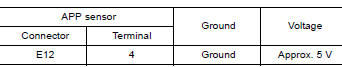
Is the inspection result normal?
YES >> GO TO 3.
NO >> Repair open circuit or short to ground or shot to power in harness or connectors.
3.CHECK APP SENSOR 2 POWER SUPPLY CIRCUIT-I
Check the voltage between APP sensor harness connector and ground.
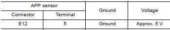
Is the inspection result normal?
YES >> GO TO 7.
NO >> GO TO 4.
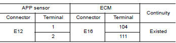
4.CHECK APP SENSOR 2 POWER SUPPLY CIRCUIT-II
- Turn ignition switch OFF.
- Disconnect ECM harness connector.
- Check the continuity between APP sensor harness connector and ECM
harness connector.
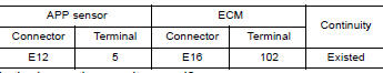
Is the inspection result normal?
YES >> GO TO 5.
NO >> Repair open circuit or short to ground or shot to power in harness or connectors.
5.CHECK SENSOR POWER SUPPLY CIRCUIT
Check harness for short to power and short to ground, between the following
terminals. 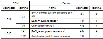
*: With A/C models
Is the inspection result normal?
YES >> GO TO 6.
NO >> Repair short to ground or short to power in harness or connectors.
6.CHECK COMPONENTS
Check the following.
- EVAP control system pressure sensor (Refer to EC, "Component Inspection").
- Battery current sensor (Refer to EC, "Component Inspection").
- Crankshaft position sensor (POS) (Refer to EC, "Component Inspection".)
- Refrigerant pressure sensor (Refer to EC, "Diagnosis Procedure".)
Is the inspection result normal?
YES >> GO TO 9.
NO >> Replace malfunctioning component.
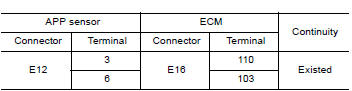
7.CHECK APP SENSOR GROUND CIRCUIT FOR OPEN AND SHORT
- Turn ignition switch OFF.
- Disconnect ECM harness connector.
- Check the continuity between APP sensor harness connector and ECM
harness connector as follows.
- Also check harness for short to ground and short to power.
Is the inspection result normal?
YES >> GO TO 8.
NO >> Repair open circuit or short to ground or shot to power in harness or connectors.
8.CHECK APP SENSOR INPUT SIGNAL CIRCUIT FOR OPEN AND SHORT
- Check the continuity between APP sensor harness connector and ECM
harness connector as follows.
- Also check harness for short to ground and short to power.
Is the inspection result normal?
YES >> GO TO 9.
NO >> Repair open circuit or short to ground or shot to power in harness or connectors.
9.CHECK APP SENSOR
Refer to EC, "Component Inspection".
Is the inspection result normal?
YES >> GO TO 11.
NO >> GO TO 10.
10.REPLACE ACCELERATOR PEDAL ASSEMBLY
Replace accelerator pedal assembly. Refer to ACC, "Exploded View".
>> INSPECTION END
11.CHECK INTERMITTENT INCIDENT
Refer to GI, "Intermittent Incident".
>> INSPECTION END
Component Inspection
1.CHECK ACCELERATOR PEDAL POSITION SENSOR
- Reconnect all harness connectors disconnected.
- Turn ignition switch ON.
- Check the voltage between ECM harness connector and ground.
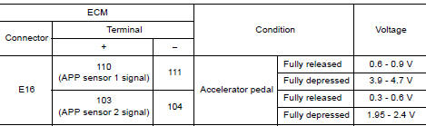
Is the inspection result normal?
YES >> INSPECTION END
NO >> GO TO 2.
2.REPLACE ACCELERATOR PEDAL ASSEMBLY
Replace accelerator pedal assembly. Refer to ACC, "Exploded View".
>> INSPECTION END
 P2135 TP sensor
Other materials:
P072C Stuck in 1GR
DTC Logic
DTC DETECTION LOGIC
DTC
Trouble diagnosis name
DTC detection condition
Possible causes
P072C
Stuck in Gear 1
The following diagnosis conditions
are met and the detection
conditions continue for 0.5 seconds
or more.- Diagnosis condition
- Shifti ...
Transverse link
Exploded View
1. Front suspension member 2. Transverse link
Removal and Installation
REMOVAL
Remove the wheel and tire assembly using power tool. Refer to WT
"Adjustment".
Remove transverse link from steering knuckle. Refer to FAX "Exploded
View".
Remove tr ...
Categories
- Manuals Home
- Nissan Versa Owners Manual
- Nissan Versa Service Manual
- Video Guides
- Questions & Answers
- External Resources
- Latest Updates
- Most Popular
- Sitemap
- Search the site
- Privacy Policy
- Contact Us

0.0058