Nissan Versa (N17): Parking lamp circuit
Description
The IPDM E/R (intelligent power distribution module engine room) controls the tail lamp relay based on inputs from the BCM via the CAN communication lines. When the tail lamp relay is energized, power flows through fuse 37, located in the IPDM E/R. Power then flows through the tail lamp relay to the front and rear combination lamps, license plate lamps.
Component Function Check
1.CHECK PARKING LAMP OPERATION
WITHOUT CONSULT
- Start IPDM E/R auto active test. Refer to PCS "Diagnosis Description" (with Intelligent Key) or PCS "Diagnosis Description" (without Intelligent Key).
- Check that the parking lamps are turned ON.
CONSULT
- Select EXTERNAL LAMPS of IPDM E/R active test item.
- While operating the test items, check that the parking lamps are turned ON.
TAIL : Parking lamp ON
OFF : Parking lamp OFF
Is the parking lamp turned ON?
YES >> Parking lamp circuit is normal.
NO >> Refer to EXL "Diagnosis Procedure".
Diagnosis Procedure
Regarding Wiring Diagram information, refer to EXL"Wiring Diagram".
1.CHECK PARKING LAMP FUSES
1. Turn the ignition switch OFF.
2. Check that the following fuses are not blown.
Is the fuse blown?
YES >> Replace the fuse after repairing the affected circuit.
NO >> GO TO 2.
2.CHECK PARKING LAMP BULB
Check the applicable lamp bulb to be sure the proper bulb standard is in use and the bulb is not open.
Is the bulb OK?
YES >> GO TO 3.
NO >> Replace the bulb.
3.CHECK TAIL LAMP RELAY OUTPUT (VOLTAGE)
1. Turn the ignition switch OFF.
2. Disconnect the front combination lamp connector, rear combination lamp connector and license plate lamp connector.
3. Turn the ignition switch ON.
4. Turn the parking lamps ON.
5. With the parking lamps ON, check voltage between the front combination
lamp connectors and ground.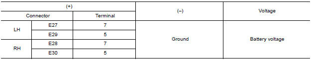
6. With the parking lamps ON, check voltage between the rear combination lamp
connectors and ground.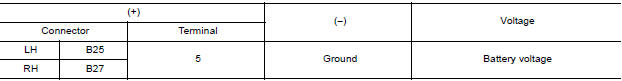
7. With the parking lamps ON, check voltage between the license plate lamp
connector and ground.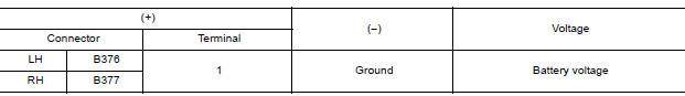
Are the inspection results normal?
YES >> GO TO 5.
NO >> GO TO 4.
4.CHECK PARKING, LICENSE PLATE AND TAIL LAMP CIRCUIT (OPEN)
1. Turn the ignition switch OFF.
2. Disconnect IPDM E/R connector.
3. Check continuity between the IPDM E/R harness connector and the front
combination lamp harness connector.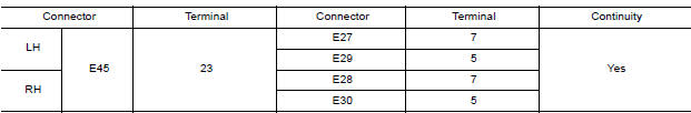
4. Check continuity between the IPDM E/R harness connector and the rear
combination lamp harness connector.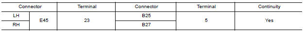
5. Check continuity between the IPDM E/R harness connector and license plate
lamp connector.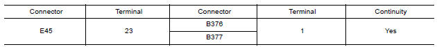
Are the inspection results normal?
YES >> Replace IPDM E/R. Refer to PCS "Removal and Installation" (with Intelligent Key) or PCS "Removal and Installation" (without Intelligent Key).
NO >> Repair or replace the harness or connector.
5.CHECK PARKING, LICENSE AND TAIL LAMP GROUND CIRCUITS
1. Check continuity between the front combination lamp harness connectors and
ground.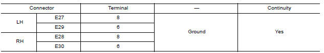
2. Check continuity between the rear combination lamp harness connectors and
ground.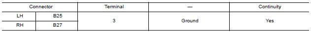
3. Check continuity between the license plate lamp harness connectors and
ground.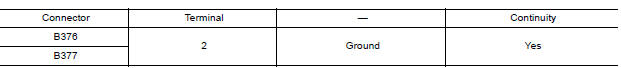
Are the inspection results normal?
YES >> Replace the malfunctioning lamp.
NO >> Repair or replace the harness or connector.
 Headlamp (LO) circuit
Description The IPDM E/R (intelligent power distribution module engine room) controls the headlamp low relay based on inputs from the BCM via the CAN communication lines. When the headlamp low re ...
Turn signal lamp circuit
Description The BCM monitors inputs from the combination switch (high beam and turn signal switch) to determine when to activate the turn signals. The BCM outputs voltage direction to the left an ...
Other materials:
NISSAN Intelligent Key (if so equipped)
WARNING
Radio waves could adversely affect
electric medical equipment. Those who
use a pacemaker should contact the
electric medical equipment manufacturer
for the possible influences before
use.
The Intelligent Key transmits radio
waves when the buttons are pressed.
The FAA ad ...
Clutch piping
Exploded View
1. CSC (Concentric Slave Cylinder) 2. Clutch tube 3. Clutch damper
4. Bracket 5. Master cylinder
Hydraulic Layout
1. Clutch tube 2. Lock pin 3. CSC (concentric slave cylinder)
4. Clutch damper 5. Master cylinder 6. Clutch pedal
Removal and Installation
CAUTION:
Do not ...
Categories
- Manuals Home
- Nissan Versa Owners Manual
- Nissan Versa Service Manual
- Video Guides
- Questions & Answers
- External Resources
- Latest Updates
- Most Popular
- Sitemap
- Search the site
- Privacy Policy
- Contact Us

0.0085