Nissan Versa (N17): Turn signal lamp circuit
Description
The BCM monitors inputs from the combination switch (high beam and turn signal switch) to determine when to activate the turn signals. The BCM outputs voltage direction to the left and right turn signals during turn signal operation or both during hazard warning operation. The BCM sends a turn signal indicator request to the combination meter via the CAN communication lines.
The BCM performs the fast flasher operation (fail-safe) if any bulb or harness of the turn signal lamp circuit is open.
NOTE: Turn signal lamp blinks at normal speed when using the hazard warning lamp.
Component Function Check
1.CHECK TURN SIGNAL LAMP
CONSULT
- Select FLASHER of BCM (FLASHER) active test item.
- While operating the test items, check that the turn signal lamp blinks.
LH : Turn signal lamp LH blinking
RH : Turn signal lamp RH blinking
OFF : The turn signal lamp OFF
Does the turn signal lamp blink?
YES >> Turn signal lamp circuit is normal.
NO >> Refer to EXL "Diagnosis Procedure".
Diagnosis Procedure
Regarding Wiring Diagram information, refer to EXL "Wiring Diagram".
1.CHECK TURN SIGNAL LAMP BULB
Check the applicable lamp bulb to be sure the proper bulb standard is in use and the bulb is not open.
Is the bulb OK?
YES >> GO TO 2.
NO >> Replace the bulb.
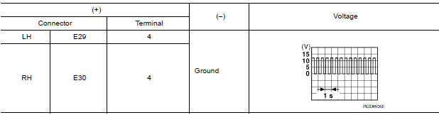
2.CHECK TURN SIGNAL LAMP OUTPUT VOLTAGE
1. Turn the ignition switch OFF.
2. Disconnect the front combination lamp connector and the rear combination lamp connector.
3. Turn the ignition switch ON.
4. With turn signal switch operating, check the voltage between the front
combination lamp harness connector
and ground.
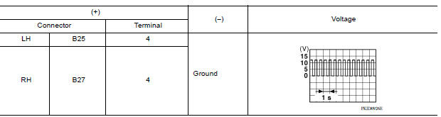
5. With turn signal switch operating, check the voltage between the rear
combination lamp harness connector
and ground.
Are the inspection results normal?
YES >> GO TO 5.
NO >> GO TO 3.
3.CHECK TURN SIGNAL LAMP CIRCUIT FOR OPEN
1. Turn the ignition switch OFF.
2. Disconnect BCM connector.
3. Check continuity between the BCM harness connector and the front
combination lamp connector.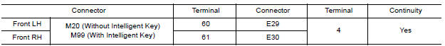
4. Check continuity between the BCM harness connector and the rear
combination lamp connector.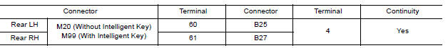
Are the inspection results normal?
YES >> GO TO 4.
NO >> Repair or replace the harness or connector.
4.CHECK TURN SIGNAL LAMP SHORT CIRCUIT
Check continuity between the BCM harness connector and ground.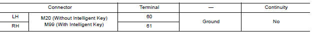
Is the inspection results normal?
YES >> Repair or replace the harness or connector.
NO >> Replace BCM. Refer to BCS "Removal and Installation" (with Intelligent Key) or BCS "Removal and Installation" (without Intelligent Key).
5.CHECK TURN SIGNAL LAMP GROUND CIRCUIT
1. Check continuity between the front combination lamp harness connector and
ground.
2. Check continuity between the rear combination lamp harness connector and
ground.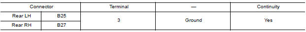
Are the inspection results normal?
YES >> Replace the malfunctioning lamp.
NO >> Repair or replace the harness or connector.
 Parking lamp circuit
Description The IPDM E/R (intelligent power distribution module engine room) controls the tail lamp relay based on inputs from the BCM via the CAN communication lines. When the tail lamp relay is ...

Other materials:
If your vehicle overheats
If your vehicle is overheating (indicated by an
extremely high temperature gauge reading (if so
equipped), a red high temperature warning light
(if so equipped) ), or if you feel a
lack of
engine power, detect abnormal noise, etc. take
the following steps.
WARNING
Do not continue to driv ...
A/T Control system
A/T Control system : component parts location
1. IPDM E/R 2. TCM 3. Transmission range switch
4. A/T unit 5. Output speed sensor 6. Stop lamp switch
7. A/T shift selector 8. Overdrive control switch 9. Combination meter (type B)
A/T Control system : component description
Name
...
Categories
- Manuals Home
- Nissan Versa Owners Manual
- Nissan Versa Service Manual
- Video Guides
- Questions & Answers
- External Resources
- Latest Updates
- Most Popular
- Sitemap
- Search the site
- Privacy Policy
- Contact Us

0.0055