Nissan Versa (N17): Id registration procedure
Description
This procedure must be performed after replacing wheels, transmitters or the BCM, or rotating wheels.
Work Procedure
NOTE: The Signal Tech II Tool (J-50190) can be used to perform the following functions. Refer to the Signal Tech II User Guide for additional information.
- Activate and display TPMS transmitter IDs
- Display tire pressure reported by the TPMS transmitter
- Read TPMS DTCs
- Register TPMS transmitter IDs
WITH TRANSMITTER ACTIVATION TOOL
NOTE: This procedure must be done after replacement of a TPMS transmitter or BCM. New replacement transmitters are provided "asleep" and must first be "woken up" using Transmitter Activation Tool J-45295 or Signal Tech II Tool J-50190 before ID registration can be performed. Use the following procedure when using the Transmitter Activation Tool J-45295.
With CONSULT.
- Turn the ignition switch ON.
- On "WORK SUPPORT" select "ID REGIST."
- Select Start on "ID REGIST" screen.
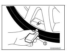
- Place transmitter activation tool (J-45295) (1) against side of tire at location closest to transmitter.
- Press and hold transmitter activation tool button until indicator
lamp turns OFF (approximately 5 seconds).
NOTE: Perform ID registration procedure starting from front left wheel, then repeat procedure for front right wheel, rear right wheel, and rear left wheel.
6. When ID registration is complete, check the
following pattern at each wheel. 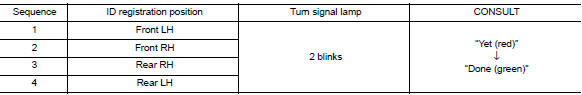
7. After the ID registration procedure for all wheels is complete, press "End" to finish ID registration, then check that ID registration for all wheels is complete.
WITHOUT TRANSMITTER ACTIVATION TOOL
NOTE: This procedure must be done after replacement of a TPMS transmitter or BCM. New replacement transmitters are provided "asleep" and must first be "woken up" using Transmitter Activation Tool J-45295 or Signal Tech II Tool J-50190 before ID registration can be performed.
With CONSULT.
- Turn the ignition switch ON.
- On "WORK SUPPORT" select "ID REGIST."
- Select Start on "ID REGIST" screen.
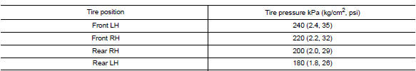
- Adjust the tire pressure for all wheels to match the list below.
- Drive the vehicle at a speed greater than 40 km/h (25 MPH) for 3 minutes or more.
- After ID registration for all wheels is complete, press "End" to finish
ID registration.

- Adjust the tire pressures for all wheels to the specified value. Refer to WT "Tire Air Pressure".
DTC/CIRCUIT DIAGNOSIS
 Transmitter wake up operation
Description This procedure must be performed after replacement of a transmitter or the BCM, or rotation of the wheels. Work Procedure NOTE: This procedure must be done after replacement of a TPM ...
C1704, C1705, C1706, C1707 Low tire
pressure
DTC Logic DTC DETECTION LOGIC DTC CONFIRMATION PROCEDURE 1.PERFORM SELF DIAGNOSTIC RESULT With CONSULT Turn the ignition sw ...
Other materials:
Drive belt
1. Water pump pulley
2. Generator pulley
3. Manual tensioner pulley
4. Air conditioner compressor pulley
5. Crankshaft pulley
WARNING
Be sure the ignition switch is placed in the
OFF or LOCK position before servicing
drive belt. The engine could rotate
unexpectedly.
1. Visually inspect t ...
P0720 Output speed sensor
DTC Logic
DTC DETECTION LOGIC
DTC
Trouble diagnosis name
DTC detection condition
Possible causes
P0720
Output Speed Sensor Circuit
Under the following diagnosis
conditions, the output speed
sensor value is less than 100
rpm continuously for 5 seconds
or ...
Categories
- Manuals Home
- Nissan Versa Owners Manual
- Nissan Versa Service Manual
- Video Guides
- Questions & Answers
- External Resources
- Latest Updates
- Most Popular
- Sitemap
- Search the site
- Privacy Policy
- Contact Us

0.0053