Nissan Versa (N17): System
Body control system
BODY CONTROL SYSTEM : System Description
OUTLINE
- BCM (Body Control Module) controls various electrical components. It receives the information required from CAN communication and the signals received from each switch and sensor.
- BCM has a combination switch reading function for reading the status of
combination switch (light, turn signal,
wiper and washer) in addition to functions for controlling the operation of
various electrical components.
It also has a signal transmission function for other systems, and a power consumption control function that reduces the power consumption with the ignition switch OFF.
- BCM is equipped with a diagnosis function that operates with CONSULT and allows for various settings to be changed.
BCM FUNCTION LIST
| System | Reference page |
| Combination switch reading system | BCS "COMBINATION SWITCH READING SYSTEM : System Diagram" |
| Signal buffer system | BCS "SIGNAL BUFFER : System Diagram" |
| Power consumption control system | BCS "POWER CONSUMPTION CONTROL SYSTEM : System Diagram" |
| Headlamp system | EXL "HEADLAMP SYSTEM : System Diagram" |
| Daytime running light system | EXL "WITH DAYTIME LIGHT SYSTEM : System Diagram" |
| Turn signal and hazard warning lamp system | EXL "TURN SIGNAL AND HAZARD WARNING LAMP SYSTEM : System Diagram" |
| Parking, license plate, side maker and tail lamps system | EXL "PARKING, LICENSE PLATE AND TAIL LAMP SYSTEM : System Diagram" |
| Exterior lamp battery saver system | EXL "HEADLAMP SYSTEM : System Description" |
| Interior room lamp control system | INL "INTERIOR ROOM LAMP CONTROL SYSTEM : System Diagram" |
| Interior room lamp battery saver system | INL "INTERIOR ROOM LAMP CONTROL SYSTEM : System Description" |
| Front wiper and washer system | WW "System Diagram" |
| Manual air conditioner system | HAC "MANUAL AIR CONDITIONING SYSTEM : System Diagram" |
| Warning chime system | WCS "WARNING CHIME SYSTEM : System Diagram" |
| Power door lock system | DLK "POWER DOOR LOCK SYSTEM : System Diagram" |
| Nissan vehicle immobilizer system-NATS (NVIS) | SEC"NISSAN VEHICLE IMMOBILIZER SYSTEM-NATS : System Diagram" |
| Panic alarm | DLK "REMOTE KEYLESS ENTRY SYSTEM : System Diagram" |
| Rear window defogger system | DEF "System Diagram" |
| Remote keyless entry system | DLK "REMOTE KEYLESS ENTRY SYSTEM : System Diagram" |
| Power window system | PWC "System Diagram" |
Combination switch reading system
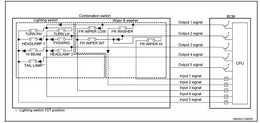
COMBINATION SWITCH READING SYSTEM : System Diagram
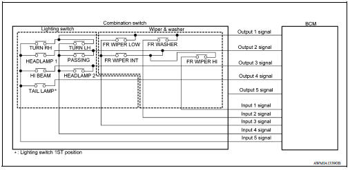
COMBINATION SWITCH READING SYSTEM : System Description
OUTLINE
- BCM reads the status of the combination switch (light, turn signal, wiper and washer) and recognizes the status of each switch.
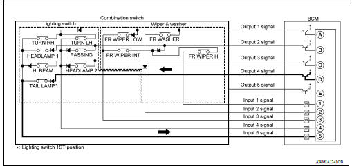
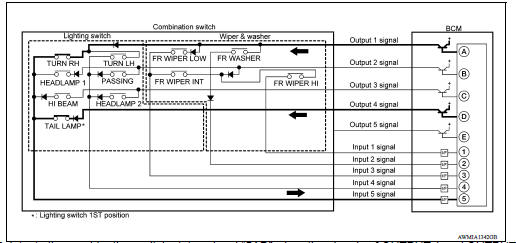
- BCM has a combination of 5 output terminals (OUTPUT 1 - 5) and 5 input terminals (INPUT 1 - 5). It reads a maximum of 20 switch states.
COMBINATION SWITCH MATRIX
Combination switch circuit
Combination switch INPUT-OUTPUT system list 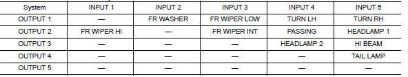
COMBINATION SWITCH READING FUNCTION
Description
- BCM reads the status of the combination switch at 10 ms intervals
normally.
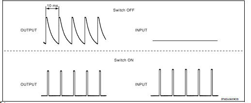
NOTE: BCM reads the status of the combination switch at 60 ms intervals when BCM is controlled at low power consumption control mode.
- BCM operates as follows and judges the status of the combination switch.
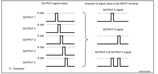
- It operates the transistor on OUTPUT side in the following order: OUTPUT 1 → 2 → 3 → 4 → 5, and outputs voltage waveform.
- The voltage waveform of OUTPUT corresponding to the formed circuit is input into the interface on INPUT side if any (1 or more) switches are ON.
- It reads this change of the voltage as the status signal of the combination switch.
Operation Example
In the following operation example, the combination of the status signals of the combination switch is replaced as follows: INPUT 1 - 5 to "1 - 5" and OUTPUT 1 - 5 to "A - E".
Example 1: When a switch (TAIL LAMP) is turned ON
- The circuit between OUTPUT 4 and INPUT 5 is formed when the TAIL LAMP
switch is turned ON.
- BCM detects the combination switch status signal "5D" when the signal of OUTPUT 4 is input to INPUT 5.
- BCM judges that the TAIL LAMP switch is ON when the signal "5D" is detected.
Example 2: When some switches (TURN RH, TAIL LAMP) are turned ON
- The circuits between OUTPUT 1 and INPUT 5 and between OUTPUT 4 and INPUT
5 are formed when the
TURN RH switch and TAIL LAMP switch are turned ON.
- BCM detects the combination switch status signal "5AD" when the signals of OUTPUT 1 and OUTPUT 4 are input to INPUT 5.
- BCM judges that the TURN RH switch and TAIL LAMP switch are ON when the signal "5AD" is detected.
SIGNAL BUFFER
SIGNAL BUFFER : System Diagram
SIGNAL BUFFER : System Description
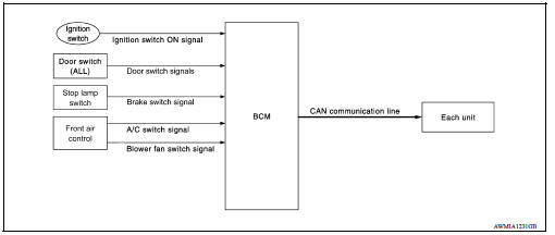
OUTLINE
BCM has the signal transmission function that outputs/transmits each input/received signal to each unit.
SIGNAL TRANSMISSION FUNCTION LIST 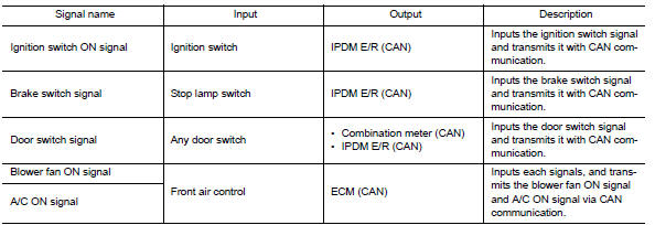
Power consumption control system
POWER CONSUMPTION CONTROL SYSTEM : System Diagram
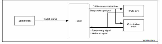
POWER CONSUMPTION CONTROL SYSTEM : System Description
OUTLINE
- BCM incorporates a power saving control function that reduces the power consumption according to the vehicle status.
- BCM switches the status (control mode) by itself with the power saving control function. It performs the sleep request to each unit (IPDM E/R and combination meter) that operates with the ignition switch OFF.
Normal mode (wake-up)
- CAN communication is normally performed with other units
- Each control with BCM is operating properly
CAN communication sleep mode (CAN sleep)
- CAN transmission is stopped
- Control with BCM only is operating
Low power consumption mode (BCM sleep)
- Low power consumption control is active
- CAN transmission is stopped
LOW POWER CONSUMPTION CONTROL WITH BCM
BCM reduces the power consumption with the following operation in the low power consumption mode.
- The reading interval of the switches changes from 10 ms interval to 60 ms interval.
Sleep mode activation
- BCM receives the sleep-ready signal (ready) from IPDM E/R and combination meter via CAN communication.
- BCM transmits the sleep wake up signal (sleep) to each unit when all of the CAN sleep conditions are fulfilled.
- Each unit stops the transmission of CAN communication with the sleep wake up signal. BCM is in CAN communication sleep mode.
- BCM is in the low power consumption mode and performs the low power consumption control when all of the BCM sleep conditions are fulfilled with CAN sleep condition.
Sleep condition 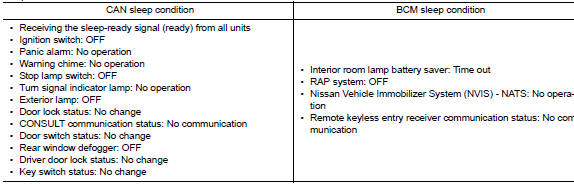
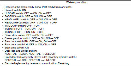
Wake-up operation
- BCM transmits sleep wake up signal (wake up) to each unit when any condition listed below is established, and then goes into normal mode from low power consumption mode.
- Each unit starts transmissions with CAN communication by receiving sleep
wake up signals. Each unit transmits
wake up signals to BCM with CAN communication to convey the start of CAN
communication.
DIAGNOSIS SYSTEM (BCM)
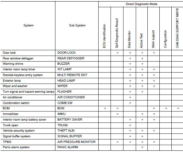
COMMON ITEM
COMMON ITEM : CONSULT Function (BCM - COMMON ITEM)
APPLICATION ITEM
CONSULT performs the following functions via CAN communication with BCM.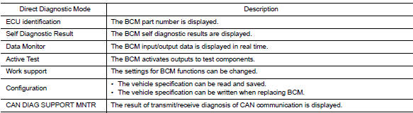
SYSTEM APPLICATION
BCM can perform the following functions.
DOOR LOCK
DOOR LOCK : CONSULT Function (BCM - DOOR LOCK)
DATA MONITOR 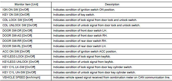
ACTIVE TEST 
WORK SUPPORT 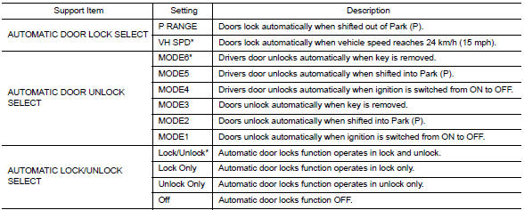
* : Initial setting
REAR DEFOGGER
REAR DEFOGGER : CONSULT Function (BCM - REAR DEFOGGER)
DATA MONITOR 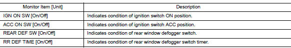
ACTIVE TEST 
BUZZER
BUZZER : CONSULT Function (BCM - BUZZER)
DATA MONITOR 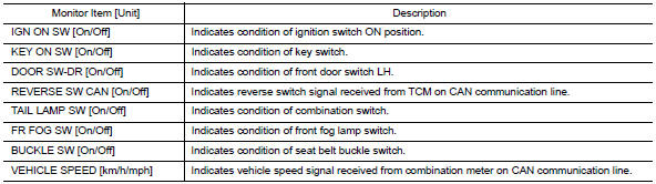
ACTIVE TEST 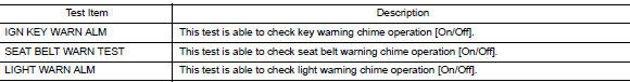
INT LAMP
INT LAMP : CONSULT Function (BCM - INT LAMP)
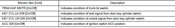
DATA MONITOR 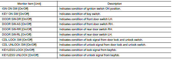
ACTIVE TEST 
WORK SUPPORT 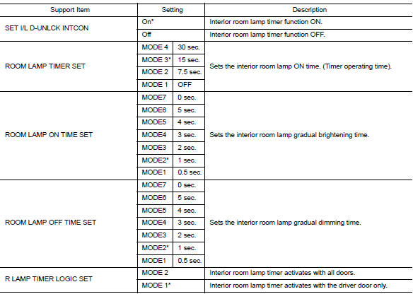
* : Initial setting
MULTI REMOTE ENT
MULTI REMOTE ENT : CONSULT Function (BCM - MULTI REMOTE ENT)
DATA MONITOR 
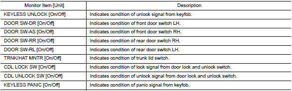
ACTIVE TEST 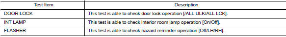
WORK SUPPORT 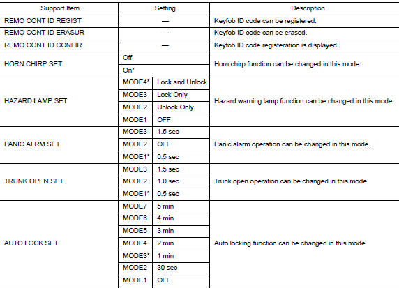
*: Initial setting
HEADLAMP
HEADLAMP : CONSULT Function (BCM - HEAD LAMP)
DATA MONITOR 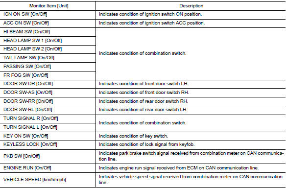
ACTIVE TEST 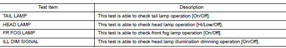
WORK SUPPORT 
* : Initial setting
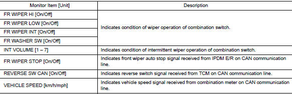
WIPER
WIPER : CONSULT Function (BCM - WIPER)
DATA MONITOR 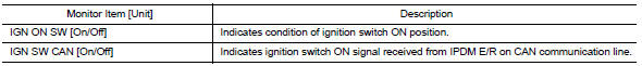
ACTIVE TEST 
WORK SUPPORT 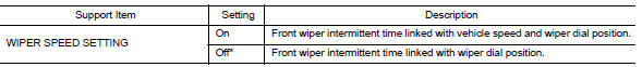
* : Initial setting
FLASHER
FLASHER : CONSULT Function (BCM - FLASHER)
DATA MONITOR 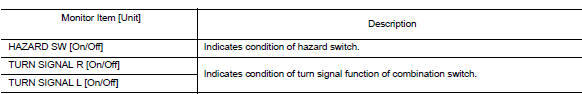
ACTIVE TEST 
AIR CONDITIONER
AIR CONDITIONER : CONSULT Function (BCM - AIR CONDITIONER)
DATA MONITOR 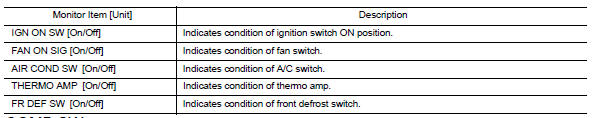
COMB SW
COMB SW : CONSULT Function (BCM - COMB SW)
DATA MONITOR 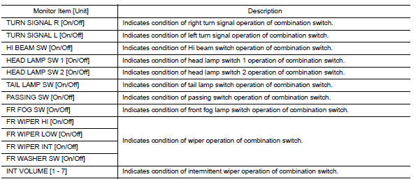
BCM
BCM : CONSULT Function (BCM - BCM)
ECU IDENTIFICATION
The BCM part number is displayed.
SELF DIAGNOSTIC RESULT
Refer to BCS "DTC Index".
WORK SUPPORT 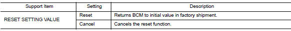
CONFIGURATION
Refer to BCS "CONFIGURATION (BCM) : Description".
CAN DIAG SUPPORT MNTR
Refer to LAN "CAN Diagnostic Support Monitor".
IMMU
IMMU : CONSULT Function (BCM - IMMU)
SELF DIAGNOSTIC RESULT
Refer to BCS "DTC Index".
ACTIVE TEST 
WORK SUPPORT 
BATTERY SAVER
BATTERY SAVER : CONSULT Function (BCM - BATTERY SAVER)
DATA MONITOR 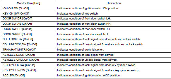
ACTIVE TEST 
WORK SUPPORT 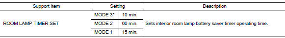
* : Initial setting
TRUNK
TRUNK : CONSULT Function (BCM - TRUNK)
DATA MONITOR 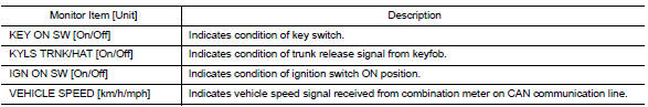
THEFT ALM
THEFT ALM : CONSULT Function (BCM - THEFT)
DATA MONITOR 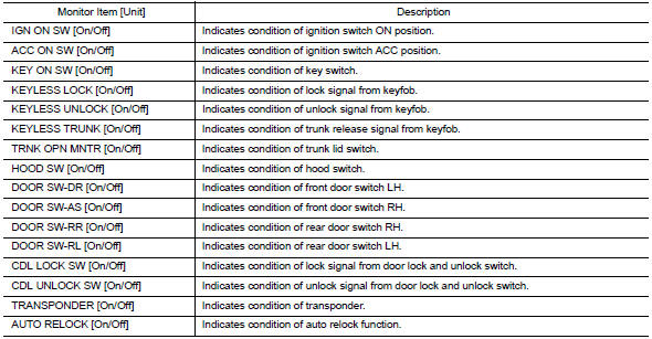
ACTIVE TEST 
WORK SUPPORT 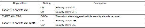
*: Initial setting
SIGNAL BUFFER
SIGNAL BUFFER : CONSULT Function (BCM - SIGNAL BUFFER)
DATA MONITOR 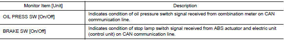
ACTIVE TEST 
AIR PRESSURE MONITOR
AIR PRESSURE MONITOR : CONSULT Function (BCM - AIR PRESSURE MONITOR)
NOTE: The Signal Tech II Tool (J-50190) can be used to perform the following functions. Refer to the Signal Tech II User Guide for additional information.
- Activate and display TPMS transmitter IDs
- Display tire pressure reported by the TPMS transmitter
- Read TPMS DTCs
- Register TPMS transmitter IDs
- Test remote keyless entry keyfob relative signal strength
SELF DIAGNOSTIC RESULT
NOTE: Before performing self diagnostic result, be sure to register the ID, or else the actual malfunction may be different from that displayed on CONSULT.
Refer to BCS "DTC Index".
DATA MONITOR 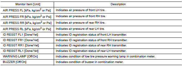
ACTIVE TEST 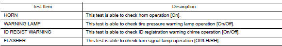
PANIC ALARM
PANIC ALARM : CONSULT Function (BCM - PANIC ALARM)
ACTIVE TEST 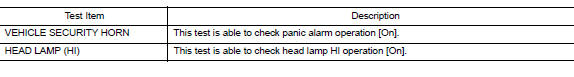
ECU DIAGNOSIS INFORMATION
 Precautions
Precaution for Supplemental Restraint System (SRS) "AIR BAG" and "SEAT BELT PRE-TENSIONER" The Supplemental Restraint System such as "AIR BAG" and "SEAT BELT PRE-TENSIONER", us ...

Other materials:
Oil cooler
Exploded View
1. Radiator hose (upper) 2. Hose clamp 3. Radiator hose (lower)
4. Hose clamp 5. Water hose 6. Oil cooler
7. Connector bolt 8. Water hose 9. Oring
A. To radiator (upper side) B. To radiator (lower side) 10. Relief valve
Removal and Installation
REMOVAL
NOTE:
When removing co ...
Key interlock cable
Exploded View
1. A/T shift selector assembly 2. Key interlock cable A: Key cylinder
B: Lock plate C: Clip
Removal and Installation
CAUTION:
Always apply the parking brake before performing removal and installation.
REMOVAL
Move the shift selector to the "N" position.
Remove the s ...
Categories
- Manuals Home
- Nissan Versa Owners Manual
- Nissan Versa Service Manual
- Video Guides
- Questions & Answers
- External Resources
- Latest Updates
- Most Popular
- Sitemap
- Search the site
- Privacy Policy
- Contact Us

0.0062