Nissan Versa (N17): Precautions
Precaution for Supplemental Restraint System (SRS) "AIR BAG" and "SEAT BELT PRE-TENSIONER"
The Supplemental Restraint System such as "AIR BAG" and "SEAT BELT PRE-TENSIONER", used along with a front seat belt, helps to reduce the risk or severity of injury to the driver and front passenger for certain types of collision. This system includes seat belt switch inputs and dual stage front air bag modules. The SRS system uses the seat belt switches to determine the front air bag deployment, and may only deploy one front air bag, depending on the severity of a collision and whether the front occupants are belted or unbelted.
Information necessary to service the system safely is included in the SR and SB section of this Service Manual.
WARNING:
- To avoid rendering the SRS inoperative, which could increase the risk of personal injury or death in the event of a collision which would result in air bag inflation, all maintenance must be performed by an authorized NISSAN/INFINITI dealer.
- Improper maintenance, including incorrect removal and installation of the SRS, can lead to personal injury caused by unintentional activation of the system. For removal of Spiral Cable and Air Bag Module, see the SR section.
- Do not use electrical test equipment on any circuit related to the SRS unless instructed to in this Service Manual. SRS wiring harnesses can be identified by yellow and/or orange harnesses or harness connectors.
PRECAUTIONS WHEN USING POWER TOOLS (AIR OR ELECTRIC) AND HAMMERS
WARNING:
- When working near the Airbag Diagnosis Sensor Unit or other Airbag System sensors with the Ignition ON or engine running, DO NOT use air or electric power tools or strike near the sensor(s) with a hammer. Heavy vibration could activate the sensor(s) and deploy the air bag(s), possibly causing serious injury.
- When using air or electric power tools or hammers, always switch the Ignition OFF, disconnect the battery and wait at least three minutes before performing any service.
Precaution for Trouble Diagnosis
AV COMMUNICATION SYSTEM
- Do not apply voltage of 7.0 V or higher to the measurement terminals.
- Use the tester with its open terminal voltage being 7.0 V or less.
- Be sure to turn ignition switch OFF and disconnect the battery cable from the negative terminal before checking the circuit.
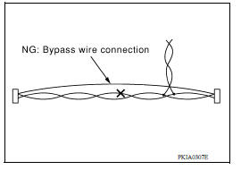
Precaution for Harness Repair
AV COMMUNICATION SYSTEM
- Solder the repaired parts, and wrap with tape. [Frays of twisted line must be within 110 mm (4.33 in).]
- Do not perform bypass wire connections for the repair parts. (The spliced wire will become separated and the characteristics of twisted line will be lost.)
Precaution for Work
- When removing or disassembling each component, be careful not to damage or deform it. If a component may be subject to interference, be sure to protect it with a shop cloth.
- When removing (disengaging) components with a screwdriver or similar tool, be sure to wrap the component with a shop cloth or vinyl tape to protect it.
- Protect the removed parts with a shop cloth and prevent them from being dropped.
- Replace a deformed or damaged clip.
- If a part is specified as a non-reusable part, always replace it with a new one.
- Be sure to tighten bolts and nuts securely to the specified torque.
- After installation is complete, be sure to check that each part works properly.
- Follow the steps below to clean components:
- Water soluble dirt:
- Dip a soft cloth into lukewarm water, wring the water out of the cloth and wipe the dirty area.
- Then rub with a soft, dry cloth.
- Oily dirt:
- Dip a soft cloth into lukewarm water with mild detergent (concentration: within 2 to 3%) and wipe the dirty area.
- Then dip a cloth into fresh water, wring the water out of the cloth and wipe the detergent off.
- Then rub with a soft, dry cloth.
- Do not use organic solvent such as thinner, benzene, alcohol or gasoline.
- For genuine leather seats, use a genuine leather seat cleaner.
PREPARATION
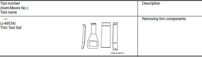
Special Service Tools
The actual shapes of Kent-Moore tools may differ from those of special service tools illustrated here.
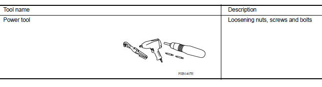
Commercial Service Tools
SYSTEM DESCRIPTION
COMPONENT PARTS
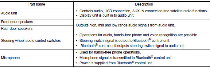
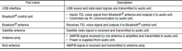
Component Parts Location
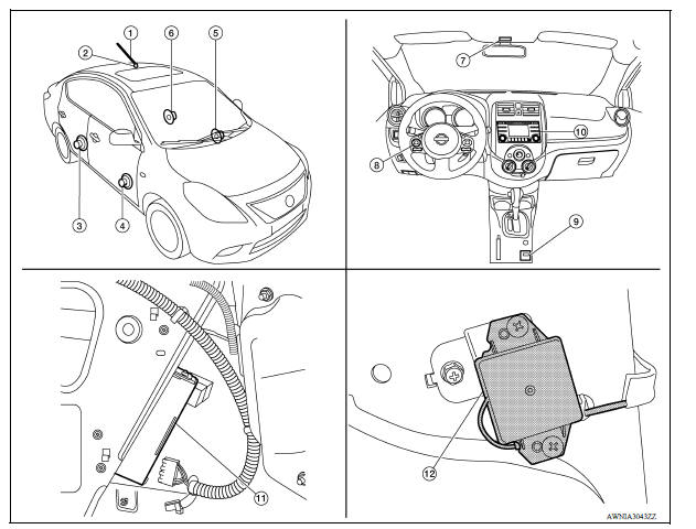
1. Rod antenna 2. Antenna base (antenna amp.) 3. Rear door speaker RH 4. Front door speaker RH 5. Front door speaker LH 6. Rear door speaker LH 7. Microphone 8. Steering wheel audio control switches 9. USB interface 10. Audio unit 11. Bluetooth control unit (view with luggage side lower finisher LH removed) 12. Bluetooth antenna (view with luggage side lower finisher LH removed)
Component Description
 Microphone
Removal and Installation 1. Remove the microphone (1) from the headlining using a suitable tool. Clip 2. Disconnect the harness connector from microphone and remove. INSTALLATION Installation ...
System
System Diagram System Description AUDIO SYSTEM The audio system consists of the following components Audio unit Front door speakers Rear door speakers Steering wheel audio control s ...
Other materials:
P0712 Transmission fluid temperature
sensor A
DTC Logic
DTC DETECTION LOGIC
DTC
Trouble diagnosis name
DTC detection condition
Possible causes
P0712
Transmission Fluid Temperature
Sensor "A" Circuit Low
Under the following diagnosis
conditions, the A/T fluid temperature
identified by TCM is
180C (3 ...
Key interlock cable
Exploded View
1. CVT shift selector assembly 2. Key interlock cable
A: Key cylinder B: Lock plate C: Clip
Removal and Installation
REMOVAL
CAUTION:
Always apply the parking brake before performing removal and installation.
Move the shift selector to the "N" position.
Remove the shi ...
Categories
- Manuals Home
- Nissan Versa Owners Manual
- Nissan Versa Service Manual
- Video Guides
- Questions & Answers
- External Resources
- Latest Updates
- Most Popular
- Sitemap
- Search the site
- Privacy Policy
- Contact Us

0.0063