Nissan Versa (N17): Precautions
Precaution for Supplemental Restraint System (SRS) "AIR BAG" and "SEAT BELT PRE-TENSIONER"
The Supplemental Restraint System such as "AIR BAG" and "SEAT BELT PRE-TENSIONER", used along with a front seat belt, helps to reduce the risk or severity of injury to the driver and front passenger for certain types of collision. This system includes seat belt switch inputs and dual stage front air bag modules. The SRS system uses the seat belt switches to determine the front air bag deployment, and may only deploy one front air bag, depending on the severity of a collision and whether the front occupants are belted or unbelted.
Information necessary to service the system safely is included in the SR and SB sections of this Service Manual.
WARNING:
- To avoid rendering the SRS inoperative, which could increase the risk of personal injury or death in the event of a collision which would result in air bag inflation, all maintenance must be performed by an authorized NISSAN/INFINITI dealer.
- Improper maintenance, including incorrect removal and installation of the SRS, can lead to personal injury caused by unintentional activation of the system. For removal of Spiral Cable and Air Bag Module, see the SR section.
- Do not use electrical test equipment on any circuit related to the SRS unless instructed to in this Service Manual. SRS wiring harnesses can be identified by yellow and/or orange harnesses or harness connectors.
PRECAUTIONS WHEN USING POWER TOOLS (AIR OR ELECTRIC) AND HAMMERS
WARNING:
- When working near the Airbag Diagnosis Sensor Unit or other Airbag System sensors with the Ignition ON or engine running, DO NOT use air or electric power tools or strike near the sensor(s) with a hammer. Heavy vibration could activate the sensor(s) and deploy the air bag(s), possibly causing serious injury.
- When using air or electric power tools or hammers, always switch the ignition OFF, disconnect the battery, and wait at least 3 minutes before performing any service.
Precaution for Work
- When removing or disassembling each component, be careful not to damage or deform it. If a component may be subject to interference, be sure to protect it with a shop cloth.
- When removing (disengaging) components with a screwdriver or similar tool, be sure to wrap the component with a shop cloth or vinyl tape to protect it.
- Protect the removed parts with a shop cloth and prevent them from being dropped.
- Replace a deformed or damaged clip.
- If a part is specified as a non-reusable part, always replace it with a new one.
- Be sure to tighten bolts and nuts securely to the specified torque.
- After installation is complete, be sure to check that each part works properly.
- Follow the steps below to clean components:
- Water soluble dirt:
- Dip a soft cloth into lukewarm water, wring the water out of the cloth and wipe the dirty area.
- Then rub with a soft, dry cloth.
- Oily dirt:
- Dip a soft cloth into lukewarm water with mild detergent (concentration: within 2 to 3%) and wipe the dirty area.
- Then dip a cloth into fresh water, wring the water out of the cloth and wipe the detergent off.
- Then rub with a soft, dry cloth.
- Do not use organic solvent such as thinner, benzene, alcohol or gasoline.
- For genuine leather seats, use a genuine leather seat cleaner.
PREPARATION
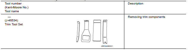
Special Service Tool
The actual shapes of Kent-Moore tools may differ from those of special service tools illustrated here.
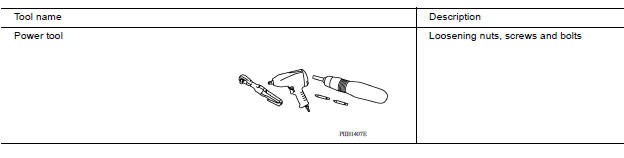
Commercial Service Tool
SYSTEM DESCRIPTION
VENTILATION SYSTEM
VENTILATION SYSTEM (FRONT AIR CONDITIONING)
VENTILATION SYSTEM (FRONT AIR CONDITIONING) : System Description
OUTLINE
The ventilation system is controlled by the A/C control. For details of the air conditioner system, refer to VTL "VENTILATION SYSTEM (FRONT AIR CONDITIONING) : System Description".
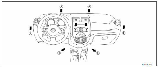
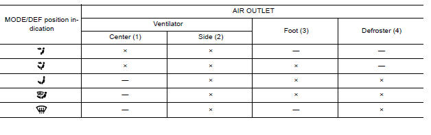
AIR FLOW
Front
REMOVAL AND INSTALLATION
DUCT AND GRILLE
Exploded View
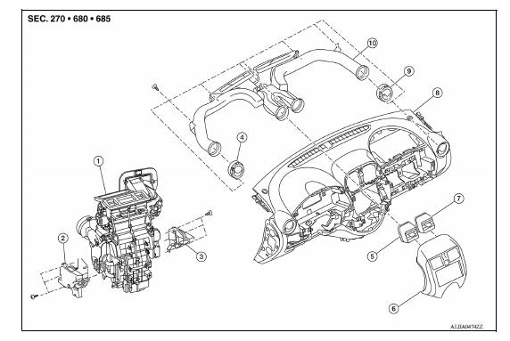
1. A/C unit assembly 2. Foot duct (LH) 3. Foot duct (RH) 4. Side ventilator grille (LH) 5. Center ventilator grille (LH) 6. Cluster lid C 7. Center ventilator grille (LH) 8. Instrument panel assembly 9. Side ventilator grille (RH) 10. Center ventilator duct assembly
CENTER VENTILATOR GRILLE
CENTER VENTILATOR GRILLE : Removal and Installation
REMOVAL
- Remove cluster lid C. Refer to IP "Removal and Installation".
- Release the tabs and remove the center ventilator grille from cluster lid C.
INSTALLATION
Installation is in the reverse order of removal.
SIDE VENTILATOR GRILLE
SIDE VENTILATOR GRILLE : Removal and Installation
REMOVAL
- Remove the instrument panel assembly. Refer to IP "Removal and Installation".
- Remove the center ventilator duct assembly.
- Remove the side ventilator grille screw and remove the side ventilator grille from the instrument panel assembly.
INSTALLATION
Installation is in the reverse order of removal.
CENTER VENTILATOR DUCT
CENTER VENTILATOR DUCT : Removal and Installation
REMOVAL
- Remove the instrument panel assembly. Refer to IP "Removal and Installation".
- Remove the center ventilator duct assembly screws and the center ventilator duct assembly from the instrument panel assembly.
INSTALLATION
Installation is in the reverse order of removal.
FOOT DUCT
FOOT DUCT : Removal and Installation
LEFT SIDE
Removal
- Remove the A/C unit assembly. Refer to HA "Removal and Installation".
- Remove the foot duct (LH) screws and the foot duct (LH).
Installation
Installation is in the reverse order of removal.
RIGHT SIDE
Removal
- Remove the instrument panel assembly. Refer to IP "Removal and Installation".
- Remove the foot duct (RH) screws and the foot duct (RH).
Installation
Installation is in the reverse order of removal.
 Heater & air conditioning control system (HAC)
Blower motor
Exploded View 1. A/C unit assembly 2. Blower motor 3. Blower fan resistor Removal and Installation REMOVAL Disconnect the negative battery terminal. Refer to PG "Removal and Install ...
Other materials:
Control panel buttons - color screen with Navigation System (if so equipped)
WARNING
Positioning of the heating or air conditioning
controls and display controls
should not be done while driving in order
that full attention may be given to
the driving operation.
Do not disassemble or modify this system.
If you do, it may result in accidents,
fire, or elec ...
Rear oil seal
REAR OIL SEAL : Removal and Installation
REMOVAL
Remove transaxle assembly.
Remove clutch cover and clutch disk (M/T models).
Remove flywheel (M/T models) or drive plate (A/T or CVT models).
Remove rear oil seal with a suitable tool.
CAUTION:
Be careful not to damage crankshaft an ...
Categories
- Manuals Home
- Nissan Versa Owners Manual
- Nissan Versa Service Manual
- Video Guides
- Questions & Answers
- External Resources
- Latest Updates
- Most Popular
- Sitemap
- Search the site
- Privacy Policy
- Contact Us

0.0058