Nissan Versa (N17): Rear RH
REAR RH : Component Function Check
1.CHECK FUNCTION
- Select DOOR LOCK of BCM using CONSULT.
- Select DOOR LOCK in ACTIVE TEST mode.
- Touch ALL LOCK or ALL UNLK to check that it works normally.
Is the inspection result normal?
YES >> Door lock actuator is OK.
NO >> Refer to DLK "REAR RH : Diagnosis Procedure".
REAR RH : Diagnosis Procedure
Regarding Wiring Diagram information, refer to DLK "POWER DOOR LOCK SYSTEM : Wiring Diagram".
1.CHECK DOOR LOCK ACTUATOR INPUT SIGNAL
- Turn ignition switch OFF.
- Disconnect rear door lock actuator RH connector.
- Check voltage between rear door lock actuator RH harness connector and
ground.
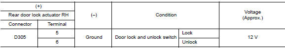
Is the inspection result normal?
YES >> Replace rear door lock actuator RH.
NO >> GO TO 2.
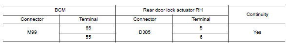
2.CHECK DOOR LOCK ACTUATOR CIRCUIT
- Disconnect BCM connector and all door lock actuator connectors.
- Check continuity between BCM harness connector and rear door lock
actuator RH harness connector.
- Check continuity between BCM harness connector and ground.
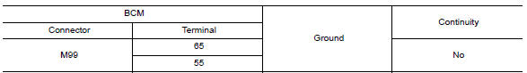
Is the inspection result normal?
YES >> GO TO 3.
NO >> Repair or replace harness.
3.CHECK BCM OUTPUT SIGNAL
- Connect BCM connector.
- Check voltage between rear door lock actuator RH harness connector and
ground.
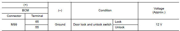
Is the inspection result normal?
YES >> Check for internal short of each door lock actuator.
NO >> Replace BCM. Refer to BCS "Removal and Installation".
 Rear LH
REAR LH : Component Function Check 1.CHECK FUNCTION Select DOOR LOCK of BCM using CONSULT. Select DOOR LOCK in ACTIVE TEST mode. Touch ALL LOCK or ALL UNLK to check that it works normally. ...

Other materials:
Security systems (if so equipped)
Your vehicle has one type of security systems:
NISSAN Vehicle Immobilizer System
NISSAN vehicle immobilizer system
The NISSAN Vehicle Immobilizer System will not
allow the engine to start without the use of a
registered key.
If the engine fails to start using a registered key
(for ex ...
Front oil seal
FRONT OIL SEAL : Removal and Installation
REMOVAL
1. Remove the following parts.
Remove wheel and tire.
Front fender protector (RH).
Drive belt.
Crankshaft pulley.
2. Remove front oil seal with ...
Categories
- Manuals Home
- Nissan Versa Owners Manual
- Nissan Versa Service Manual
- Video Guides
- Questions & Answers
- External Resources
- Latest Updates
- Most Popular
- Sitemap
- Search the site
- Privacy Policy
- Contact Us

0.0063