Nissan Versa (N17): Steering column
Exploded View
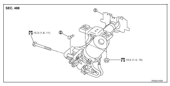
1. Steering column assembly 2. Clamp
Removal and Installation
REMOVAL
CAUTION:
- Keep steering column assembly away from magnetic sources.
- Do not disassemble steering column assembly.
- While removing the steering column assembly, do not move the steering gear.
- When removing the steering column assembly, be careful not to allow the intermediate shaft to turn.
- Set vehicle to the straight-ahead position.
- Place the steering column tilt to the lowest selection.
- Remove instrument lower panel LH. Refer to IP, "Removal and Installation".
- Remove driver air bag module. Refer to SR"Removal and Installation".
- Remove steering wheel. Refer to ST "Exploded View".
- Remove steering column covers. Refer to IP "Removal and Installation".
- Remove spiral cable. Refer to SR "Removal and Installation".
- Remove combination switch. Refer to EXL "Exploded View"
- Remove the cluster lid A. Refer to IP "Removal and Installation"
- Disconnect the harness connectors from the steering switch.
- Remove the key cylinder only if the steering column is being replaced. Refer to TM "Removal and Installation".
- Place the steering column tilt to the middle selection.
CAUTION: Do not change the position of the tilt mechanism until the steerign column is reinstalled.
- Loosen the steering shaft lower joint bolt.
- Remove the intermediate shaft upper bolt and separate intermediate shaft
from steering column assembly.
Refer to ST "Removal and Installation".
CAUTION:
- Place a matching mark on both intermediate shaft and steering column assembly before removing intermediate shaft.
- When removing intermediate shaft, do not insert any tool into the yoke groove to pull out the intermediate shaft or damage could occur. Replace intermediate shaft with a new one if damaged.
- Disconnect the harness connectors from EPS control unit.
- Remove steering column assembly.
- Remove EPS control unit from steering column assembly. Refer to STC "Removal and Installation".
- Remove clamp from steering column assembly.
- Perform inspection after removal. Refer to ST "Inspection".
INSTALLATION
CAUTION:
- Do not impact on the axis when removing steering column assembly.
- When installing the steering column cover, check that the vehicle harness is not stuck in the cover.
Installation is in the reverse order of removal.
- For intermediate shaft bolt direction, refer to ST "Exploded View".
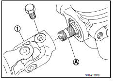
- When connecting intermediate shaft upper side (1) and column shaft, make sure the bolt is securely seated in groove (A) of column shaft before final tightening.
- After installing steering column assembly, perform self-diagnosis with CONSULT to ensure correct operation. Refer to STC "CONSULT Function".
- Perform inspection after installation. Refer to ST "Inspection".
Inspection
INSPECTION AFTER REMOVAL
- Check each part of steering column assembly for damage or other malfunctions. Replace if there are any abnormal conditions.
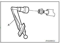
- Measure steering column rotating torque using Tool (A). Replace steering column assembly if the rotating torque is outside the standard.
Tool number : - (J-25765-A)
Rotating torque : Refer to ST "Steering Column Operating Range".
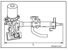
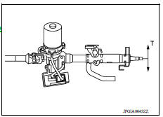
- Measure the steering column length (L) as shown, if vehicle has been involved in a minor collision. Replace steering column assembly (with motor, reduction gear, sensor) if (L) is outside the standard.
Steering column length (L) : Refer to ST "Steering Column Operating Range".
INSPECTION AFTER INSTALLATION
- Check each part of steering column assembly for damage or other malfunctions. Replace if there are any abnormal conditions.
- Check the steering wheel play, neutral position steering wheel, steering wheel turning force, and front wheel turning angle. Refer to ST "Inspection".
- Check tilt mechanism operating range (T) as shown.
Tilt operating range (T) : Refer to ST "Steering Column Operating Range".
 Steering wheel
Exploded View 1. Steering wheel Removal and Installation REMOVAL NOTE: When reconnecting spiral cable, secure cable with a tape so that case and rotating part stay aligned. This will omi ...
Steering shaft
Exploded View 1. Lower joint 2. Intermediate shaft 3. Steering column assembly ...
Other materials:
Description
Engine Cooling System
M/T models
CVT and A/T models
Engine Cooling System Schematic
M/T models
CVT and A/T models
OVERHEATING CAUSE ANALYSIS
Troubleshooting Chart
Symptom
Check items
Cooling system
parts
malfunction
Poor heat transfer
...
P062F EEPROM
Description
TCM checks the value read in FLASH ROM at ignition switch ON, and judges if
there is writing failure to
FLASH ROM or malfunction of FLASH ROM.
DTC Logic
DTC DETECTION LOGIC
DTC
Trouble diagnosis name
DTC detection condition
Possible causes
P062F
Inter ...
Categories
- Manuals Home
- Nissan Versa Owners Manual
- Nissan Versa Service Manual
- Video Guides
- Questions & Answers
- External Resources
- Latest Updates
- Most Popular
- Sitemap
- Search the site
- Privacy Policy
- Contact Us

0.0055