Nissan Versa (N17): Steering shaft
Exploded View
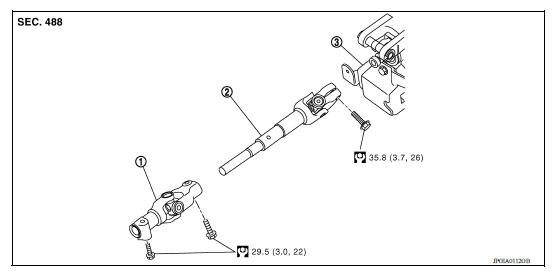
1. Lower joint 2. Intermediate shaft 3. Steering column assembly
Removal and Installation
REMOVAL
CAUTION: Spiral cable may be cut if steering wheel turns while separating steering column assembly and steering gear assembly. Be sure to secure steering wheel using string to avoid turning.
- Set vehicle to the straight-ahead position.
- Place the steering column tilt to the middle selection.
- Remove instrument lower panel LH. Refer to IP "Removal and Installation".
- Loosen lower joint upper bolt.
- Remove lower joint lower bolt and separate lower joint from steering gear assembly.
CAUTION:
- Place a matching mark on both lower joint and steering gear assembly before removing lower joint.
- When removing lower joint, do not insert any tool into the yoke
groove to pull out the lower joint.
Replace the lower joint with a new one if damaged.
- Remove lower joint from intermediate shaft.
- Remove intermediate shaft bolt (steering column side), and remove intermediate shaft from steering column assembly.
CAUTION:
- Place a matching mark on both intermediate shaft and steering column assembly before removing intermediate shaft.
- When removing intermediate shaft, do not insert any tool into the yoke groove to pull out the intermediate shaft or damage could occur. Replace intermediate shaft with a new one if damaged.
INSTALLATION
CAUTION: Spiral cable may be cut if steering wheel turns while separating steering column assembly and steering gear assembly. Be sure to secure steering wheel using string to avoid turning.
Installation is in the reverse order of removal.
- Before installation, check that the tilt position is at the middle level.
- For intermediate shaft bolt, and lower joint bolt direction, refer to ST "Exploded View".
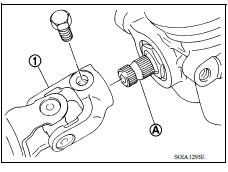
- To install align the steering gear guide protrusion (A) with the
groove of lower joint (1), make sure the bolt is securely seated in
groove (B) of steering gear before final tightening.
CAUTION: If a guide protrusion is not included, align with the matching mark placed at the removal step.
- When tightening lower joint bolt (steering gear assembly side), temporarily tighten it and make sure there is no sticking or galling before final tightening.
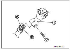
- When connecting intermediate shaft upper side (1) and column shaft, make sure the bolt is securely seated in groove (A) of column shaft before final tightening.
- Perform inspection after installation. Refer to ST "Inspection".
Inspection
INSPECTION AFTER REMOVAL
- Check each part of lower joint for damage or other malfunctions. Replace if there are any abnormal conditions.
- Check each part of intermediate shaft for damage or other malfunctions. Replace if there are any abnormal conditions.
INSPECTION AFTER INSTALLATION
- Check each part of lower joint for damage or other malfunctions. Replace if there are any abnormal conditions.
- Check each part of intermediate shaft for damage or other malfunctions. Replace if there are any abnormal conditions.
- Rotate steering wheel to check for decentered condition, binding, noise, or excessive steering effort.
- Check the steering wheel play, neutral position steering wheel, steering wheel turning force, and front wheel turning angle.
- Steering wheel play: Refer to ST "Inspection".
- Neutral position steering wheel, steering wheel turning force, and front wheel turning angle: Refer to ST "Inspection".
 Steering column
Exploded View 1. Steering column assembly 2. Clamp ...
Steering gear and linkage
Exploded View 1. Guide 2. Cowl seal 3. Steering gear assembly 4. Front suspension member Front Removal and Installation NOTE: When removing components such as hoses, tubes/lines, etc., cap o ...
Other materials:
P0507 ISC system
Description
The ECM controls the engine idle speed to a specified level through the fine
adjustment of the air, which is let
into the intake manifold, by operating the electric throttle control actuator.
The operating of the throttle valve is
varied to allow for optimum control of the engine ...
P0706 Transmission range sensor A
DTC Logic
DTC DETECTION LOGIC
DTC
Trouble diagnosis name
DTC detection condition
Possible causes
P0706
Transmission Range Sensor
"A" Circuit Range/Performance
The following diagnosis conditions
are met and the position
signal is OFF continuously for
15 ...
Categories
- Manuals Home
- Nissan Versa Owners Manual
- Nissan Versa Service Manual
- Video Guides
- Questions & Answers
- External Resources
- Latest Updates
- Most Popular
- Sitemap
- Search the site
- Privacy Policy
- Contact Us

0.0057