Nissan Versa (N17): Steering gear and linkage
Exploded View
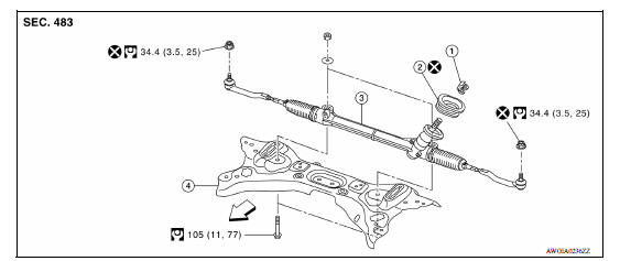
1. Guide 2. Cowl seal 3. Steering gear assembly
4. Front suspension member  Front
Front
Removal and Installation
NOTE: When removing components such as hoses, tubes/lines, etc., cap or plug openings to prevent fluid from spilling.
REMOVAL
- Set vehicle to the straight-ahead position.
- Place the steering column tilt to middle selection.
- Loosen lower joint upper bolt.
- Remove lower joint lower bolt. Refer to ST "Removal and Installation".
CAUTION:
- Spiral cable may be cut if steering wheel turns while separating steering column assembly and steering gear assembly. Always secure the steering wheel using string to avoid turning.
- Place a matching mark on both lower joint and steering gear assembly before removing lower joint.
- When removing lower joint, do not place any tool into the yoke
groove to pull out the lower joint.
Replace the lower joint with a new one if damaged.
- Remove the wheel and tire assemblies using power tool. Refer to WT "Adjustment".
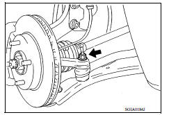
- Remove steering outer socket from steering knuckle using Tool.
Tool number : HT72520000 (J-25730-A)
- Support front suspension member with a suitable jack.
- Remove front suspension member bolts. Refer to FSU "Removal and Installation".
- Remove the bolts and nuts of steering gear assembly.
- Separate cowl seal from vehicle.
- Lower the suitable jack to the position where the steering gear assembly
can be removed.
CAUTION: Secure front suspension member to a jack.
- Remove guide from pinion assembly.
- Remove cowl seal from steering gear assembly.
INSTALLATION
Installation is in the reverse order of removal.
CAUTION:
- Spiral cable may be cut if steering wheel turns while separating steering column assembly and steering gear assembly. Always secure the steering wheel using string to avoid turning.
- The guide protrusion is not required to be reinstalled.
- Before installation, check that the steering column tilt position is at the middle level.
- Clean mating surface on the body side of cowl seal when installing steering gear assembly.
- Perform final tightening of nuts and bolts on each part under unladen conditions with tires on level ground when removing steering gear assembly. Check wheel alignment. Refer to FSU "Inspection and Adjustment".
- Rotate steering wheel to check that the spiral cable is centered, binding, noise or excessive steering effort.
- Do not reuse steering outer socket nut and cowl seal.
- Perform inspection after installation. Refer to ST "Inspection".
Inspection
INSPECTION AFTER INSTALLATION
- Check if steering wheel turns smoothly when it is turned several times throughout the full steering range.
- Check the steering wheel play, neutral position steering wheel, steering wheel turning force, and front wheel turning angle.
- Steering wheel play: Refer to ST "Inspection".
- Neutral position steering wheel, steering wheel turning force and front wheel turning angle: Refer to ST"Inspection".
UNIT DISASSEMBLY AND ASSEMBLY
 Steering shaft
Exploded View 1. Lower joint 2. Intermediate shaft 3. Steering column assembly ...
Steering gear and linkage
Exploded View 1. Joint cover 2. Steering gear assembly 3. Inner socket 4. Large clamp 5. Boot 6. Small boot clamp 7. Outer socket ...
Other materials:
Power steering
WARNING
If the engine is not running or is turned
off while driving, the power assist for
the steering will not work. Steering will
be harder to operate.
When the power steering warning light
illuminates with the engine running,
there will be no power assist for the
steering. You w ...
Stall test
Work Procedure
INSPECTION
Check the engine oil level. Replenish if necessary.
Check for leak of the CVT fluid. Refer to TM "Inspection".
Drive for about 10 minutes to warm up the vehicle so that the CVT fluid
temperature is 50 to 80C (122 to
176F).
Be sure to apply the par ...
Categories
- Manuals Home
- Nissan Versa Owners Manual
- Nissan Versa Service Manual
- Video Guides
- Questions & Answers
- External Resources
- Latest Updates
- Most Popular
- Sitemap
- Search the site
- Privacy Policy
- Contact Us

0.0056