Nissan Versa (N17): System
System Diagram
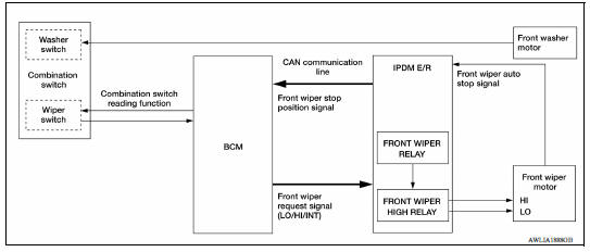
System Description
FRONT WIPER CONTROL (BASIC)
1. BCM detects the combination switch position by the combination switch reading function.
2. BCM transmits the front wiper request signal to the IPDM E/R using CAN communication.
3. IPDM E/R controls the integrated front wiper relay and front wiper high relay based on the status of the front wiper request signal.
4. IPDM E/R provides power to operate the front wiper motor.
LOW SPEED OPERATION
1. Ignition switch ON.
2. Front wiper switch in LO or MIST position.
3. BCM reads the combination switch position and transmits the front wiper request signal (LO) to IPDM E/R using CAN communication.
4. IPDM E/R turns ON the front wiper relay.
HIGH SPEED OPERATION
1. Ignition switch ON.
2. Front wiper switch in HI.
3. BCM reads the combination switch position and transmits the front wiper request signal (HI) to IPDM E/R using CAN communication.
4. IPDM E/R turns ON the front wiper relay and the front wiper high relay.
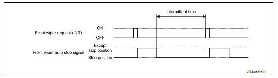
INTERMITTENT OPERATION
1. Ignition switch ON.
2. Front wiper switch INT.
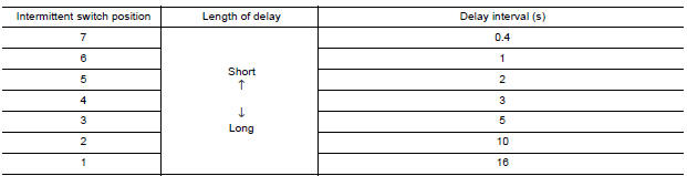
3. BCM reads the combination switch position. BCM calculates the delay interval based on the table below and then transmits the front wiper request signal (INT) to IPDM E/R using CAN communication.
4. IPDM E/R turns ON the front wiper relay only once.
5. BCM detects stop position of the front wiper motor based on the front wiper stop position signal received from the IPDM E/R.
6. BCM transmits the front wiper request signal (INT) again after the delay interval.
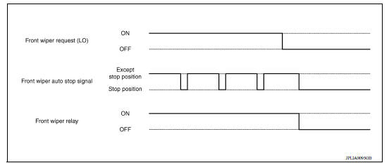
AUTO STOP OPERATION
1. Front wiper switch is turned OFF.
2. BCM monitors wiper switch position by combination switch reading position function.
3. BCM stops transmitting the front wiper request signal to the IPDM E/R.
4. IPDM E/R detects the front wiper auto stop signal from the position of the front wiper motor (stop position/ except stop position).
5. When the front wiper request signal is stopped, IPDM E/R turns ON the front wiper relay until the front wiper motor returns to the stop position.
6. IPDM E/R turns the front wiper relay OFF when the front wiper motor has reached the stop position.
MIST OPERATION
1. Ignition switch ON.
2. Front washer switch in OFF position.
3. Front wiper switch in MIST position.
4. BCM reads the combination switch position and transmits the front wiper request signal (LO) to IPDM E/R using CAN communication.
5. IPDM E/R turns ON the front wiper relay.
6. The front wiper operates once after the front washer operation.
WIPER/WASHER OPERATION
1. Ignition switch ON.
2. Front washer switch ON.
3. The front washer switch provides ground for the front washer motor.
4. BCM reads the combination switch position and transmits the front wiper request signal (LO) to IPDM E/R using CAN communication.
5. BCM transmits the front wiper request signal (LO) to IPDM E/R using CAN communication.
6. IPDM E/R turns ON the front wiper relay.
7. The front wiper operates.
NOTE: BCM transmits the front wiper request signal (LO) so that the front wiper operates approximately 3 times after front washer switch OFF is detected.
Fail-Safe
FAIL−SAFE OPERATION
IPDM E/R performs the fail-safe function when the front wiper auto stop circuit is malfunctioning. Refer to PCS "Fail-safe" or PCS "Fail-Safe".
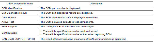
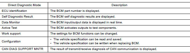
DIAGNOSIS SYSTEM (BCM) (WITH INTELLIGENT KEY SYSTEM)
COMMON ITEM
COMMON ITEM : CONSULT Function (BCM - COMMON ITEM)
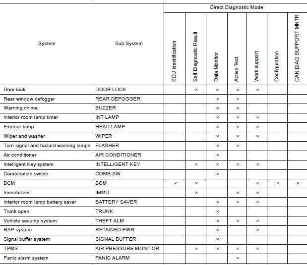
APPLICATION ITEM
CONSULT performs the following functions via CAN communication with BCM.
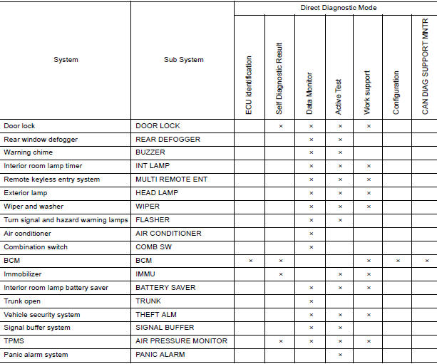
SYSTEM APPLICATION
BCM can perform the following functions.
WIPER
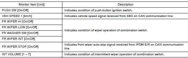
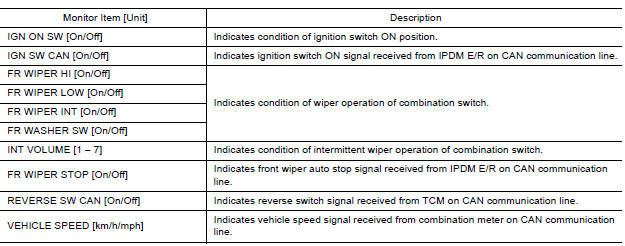
WIPER : CONSULT Function (BCM - WIPER)
DATA MONITOR
ACTIVE TEST

WORK SUPPORT
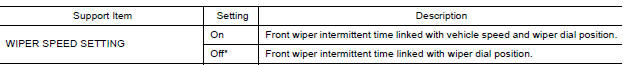
* : Initial setting
DIAGNOSIS SYSTEM (BCM) (WITHOUT INTELLIGENT KEY SYSTEM)
COMMON ITEM
COMMON ITEM : CONSULT Function (BCM - COMMON ITEM)
APPLICATION ITEM
CONSULT performs the following functions via CAN communication with BCM.
SYSTEM APPLICATION
BCM can perform the following functions.
WIPER
WIPER : CONSULT Function (BCM - WIPER)
DATA MONITOR
ACTIVE TEST

WORK SUPPORT
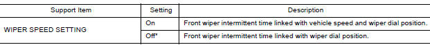
* : Initial setting
 Precautions
Precaution for Supplemental Restraint System (SRS) "AIR BAG" and "SEAT BELT PRE-TENSIONER" The Supplemental Restraint System such as "AIR BAG" and "SEAT BELT PRE-TENSIONER", us ...

Other materials:
Power outlets
Instrument panel
Console (if so equipped)
The power outlets are for powering electrical
accessories such as cellular telephones. The
outlets are rated at 12 volt, 120W (10A) maximum.
CAUTION
The outlet and plug may be hot during
or immediately after use.
Only certain power outlets ...
Cleaning exterior
In order to maintain the appearance of your vehicle,
it is important to take proper care of it.
To protect the paint surfaces, please wash your
vehicle as soon as you can:
After a rainfall to prevent possible damage
from acid rain.
After driving on coastal roads.
When contaminants suc ...
Categories
- Manuals Home
- Nissan Versa Owners Manual
- Nissan Versa Service Manual
- Video Guides
- Questions & Answers
- External Resources
- Latest Updates
- Most Popular
- Sitemap
- Search the site
- Privacy Policy
- Contact Us

0.0057