Nissan Versa (N17): System
CHARGING SYSTEM
CHARGING SYSTEM : System Diagram
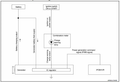
CHARGING SYSTEM : System Description
The generator provides DC voltage to operate the vehicle's electrical system and to keep the battery charged.
The voltage output is controlled by the IC regulator.
CHARGING SYSTEM : Component Description
POWER GENERATION VOLTAGE VARIABLE CONTROL SYSTEM
System Diagram
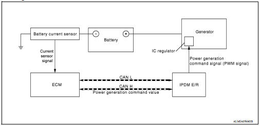
System Description
Power generation variable voltage control system has been adopted. By varying the voltage to the generator, engine load due to power generation of the generator is reduced and fuel consumption is decreased.
NOTE: When any malfunction is detected in the power generation variable voltage control system, power generation is performed according to the characteristic of the IC regulator in the generator.
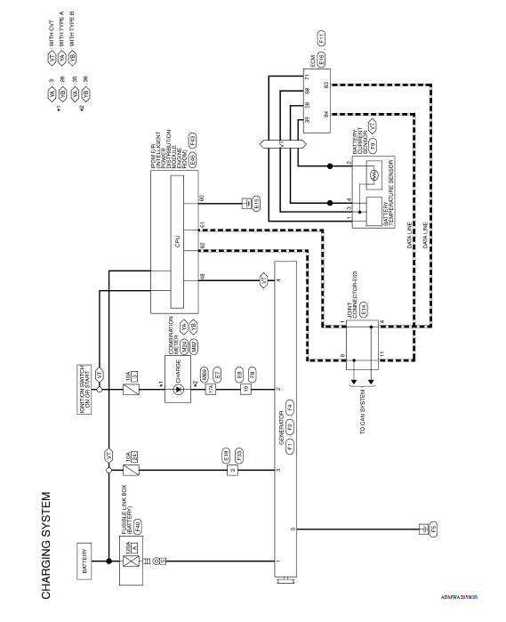
WIRING DIAGRAM
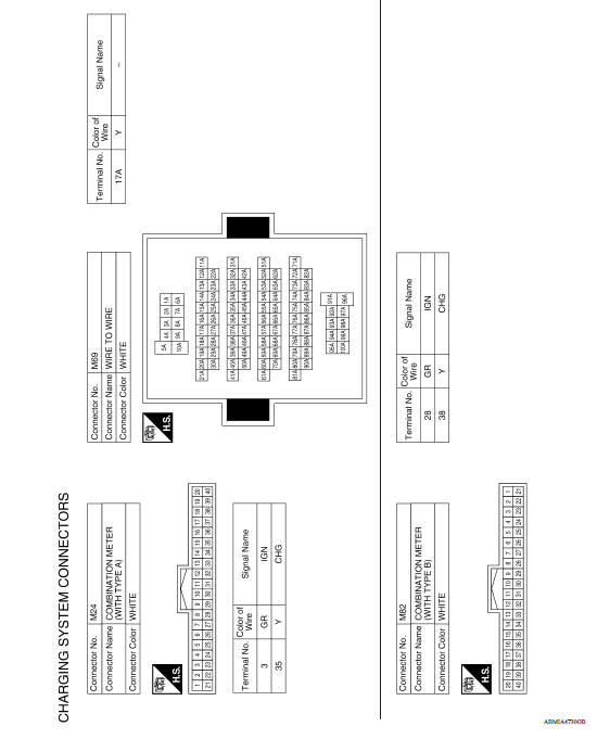
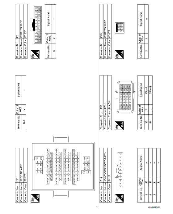
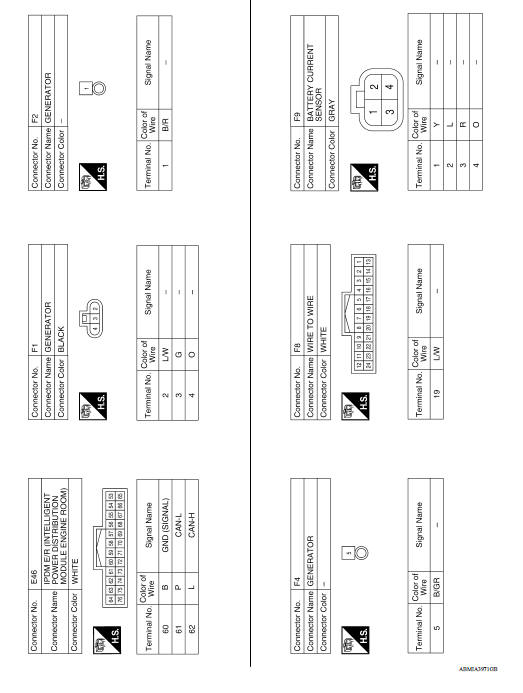
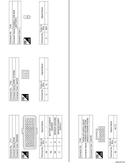
CHARGING SYSTEM
Wiring Diagram
BASIC INSPECTION
 Precautions
Precaution for Supplemental Restraint System (SRS) "AIR BAG" and "SEAT BELT PRE-TENSIONER" The Supplemental Restraint System such as "AIR BAG" and "SEAT BELT PRE-TENSIONER", us ...

Other materials:
Rear window defroster switch
To defrost the rear window glass, start the engine
and push the rear window defroster switch on.
The rear window defroster indicator light on the
switch comes on. Push the switch again to turn
the defroster off.
The rear window defroster automatically turns off
after approximately 15 m ...
Variable voltage control system (if so equipped)
CAUTION
Do not ground accessories directly to
the battery terminal. Doing so will bypass
the variable voltage control system
and the vehicle battery may not
charge completely.
Use electrical accessories with the engine
running to avoid discharging the
vehicle battery.
Your v ...
Categories
- Manuals Home
- Nissan Versa Owners Manual
- Nissan Versa Service Manual
- Video Guides
- Questions & Answers
- External Resources
- Latest Updates
- Most Popular
- Sitemap
- Search the site
- Privacy Policy
- Contact Us

0.0046