Nissan Versa (N17): System
Meter system
METER SYSTEM : System Diagram
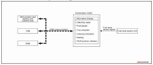
SYSTEM DIAGRAM
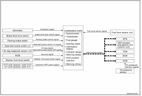
METER SYSTEM : System Description
COMBINATION METER
Combination Meter
- The combination meter monitors signals from switches, sensors and modules to control the following functions:
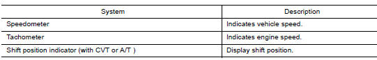
- Speedometer/Tachometer
- Shift position indicator
- Warning lamps
- Indicator lamps
- Meter illumination control
- Information display
- The combination meter has an integrated buzzer that is activated when it receives a signal from the BCM via CAN communication. Refer to WCS "WARNING CHIME SYSTEM : System Description" for further details.
- The combination meter includes a self diagnosis function.
- The combination meter can be diagnosed with CONSULT.
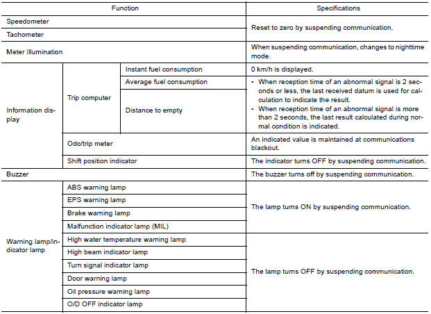
METER CONTROL FUNCTION LIST
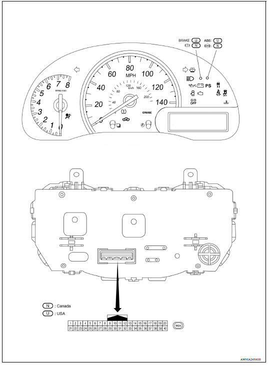
METER SYSTEM : Arrangement of Combination Meter
METER SYSTEM : Fail-Safe
The combination meter activates the fail-safe control if CAN communication with each unit is malfunctioning.
SPEEDOMETER
SPEEDOMETER : System Description
SYSTEM DIAGRAM
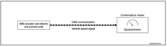
DESCRIPTION
The ABS actuator and electric unit (control unit) receives each wheel speed sensor signal and provides a vehicle speed signal to the combination meter via CAN communication.
TACHOMETER
TACHOMETER : System Description
SYSTEM DIAGRAM
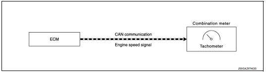
DESCRIPTION
The crank position sensor sends a crankshaft position signal to the ECM. The ECM provides an engine speed signal to the combination meter via CAN communication lines. The tachometer indicates engine speed in revolutions per minute (rpm).
SHIFT POSITION INDICATOR
SHIFT POSITION INDICATOR : System Diagram
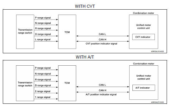
SHIFT POSITION INDICATOR : System Description
DESCRIPTION
The combination meter receives the shift position signal from TCM via CAN communication, and displays the position of the shift indicator.
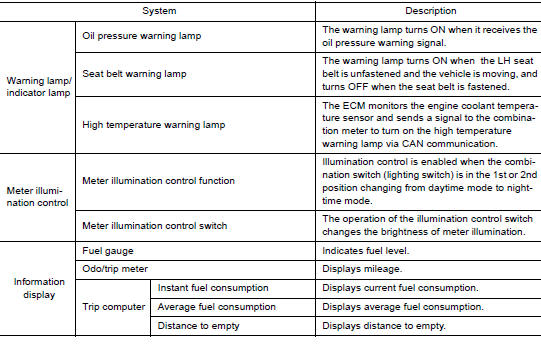
HIGH WATER TEMPERATURE WARNING LAMP
HIGH WATER TEMPERATURE WARNING LAMP : System Description
SYSTEM DIAGRAM
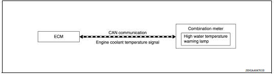
DESCRIPTION
The ECM monitors the engine coolant temperature from the engine coolant temperature sensor. When the coolant temperature is above the specified value, the ECM sends a CAN communication signal to the combination meter turning on the high temperature warning lamp.
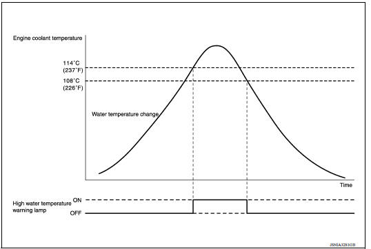
Timing Chart
OIL PRESSURE WARNING LAMP
OIL PRESSURE WARNING LAMP : System Diagram
SYSTEM DIAGRAM
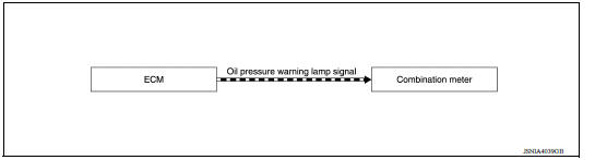
OIL PRESSURE WARNING LAMP : System Description
DESCRIPTION
The combination meter turns the oil pressure warning lamp ON when receiving a signal from the ECM via CAN communication.
METER ILLUMINATION
METER ILLUMINATION : System Description
SYSTEM DIAGRAM
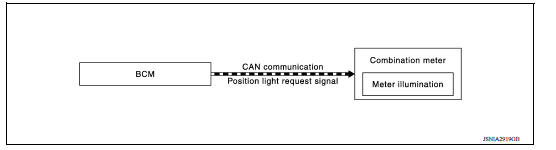
DESCRIPTION
Meter Illumination Control Function
Meter illumination control is enabled when the meter receives a signal from the BCM that the combination switch is in the 1st or 2nd position, the meter switches from Daytime mode to Nighttime mode.
Information display
INFORMATION DISPLAY : System Diagram
INFORMATION DISPLAY : System Description
DESCRIPTION
The combination meter receives signals from switches, sensors and modules for operating the following functions on the information display.
- Odo/trip meter
- Fuel gauge
- Trip computer
- Interrupt indication
- Meter illumination level
- Setting
- Low fuel warning
- Loose fuel cap warning
ODO/TRIP METER
The combination meter calculates mileage using the vehicle speed signal from the ABS actuator and electric unit (control unit) and displays the mileage on the information display.
FUEL GAUGE
Control Outline
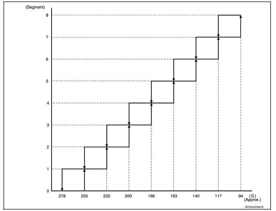
The fuel level sensor unit sends a variable resistor signal to the combination meter. The fuel gauge indicates the approximate fuel level in the fuel tank.
Refuel Control
The unit detects the driver is refueling the vehicle and accelerates the fuel gauge segment movement if the fuel level changes by 9 (2-3/8 US, 2 lmp gal) or more.
Lighting segment-resistance relationship
INTERRUPT INDICATION
The combination meter may interrupt the current information display with a warning, alert or maintenance reminder on the information display, based on signals received from each unit and switch.
Low Fuel Warning
The low fuel warning turns ON when the fuel level in the fuel tank reaches
approximately 6.3  (1-5/8 US gal,
1-3/8 Imp gal).
(1-5/8 US gal,
1-3/8 Imp gal).
LOOSE FUEL CAP WARNING
The LOOSE FUEL CAP message will display in the information display when the fuel-filler cap is not tightened correctly. The message will turn off as soon as the ECM detects the fuel-filler cap is properly tightened. The ECM provides a loose fuel cap signal to the combination meter via CAN communication lines.
 Precautions
Other materials:
If your vehicle overheats
If your vehicle is overheating (indicated by an
extremely high temperature gauge reading (if so
equipped), a red high temperature warning light
(if so equipped) ), or if you feel a
lack of
engine power, detect abnormal noise, etc. take
the following steps.
WARNING
Do not continue to driv ...
Evaporative emission system
EVAPORATIVE EMISSION SYSTEM : System Diagram
EVAPORATIVE EMISSION SYSTEM : System
Description
INPUT/OUTPUT SIGNAL CHART
Sensor
Input signal to ECM
ECM function
Actuator
Crankshaft position sensor (POS)
Camshaft position sensor (PHASE)
Engine speed*1
Piston ...
Categories
- Manuals Home
- Nissan Versa Owners Manual
- Nissan Versa Service Manual
- Video Guides
- Questions & Answers
- External Resources
- Latest Updates
- Most Popular
- Sitemap
- Search the site
- Privacy Policy
- Contact Us

0.0081