Nissan Versa (N17): TCM
Reference Value
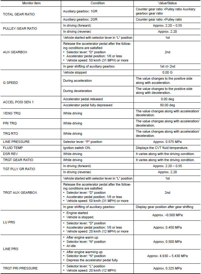
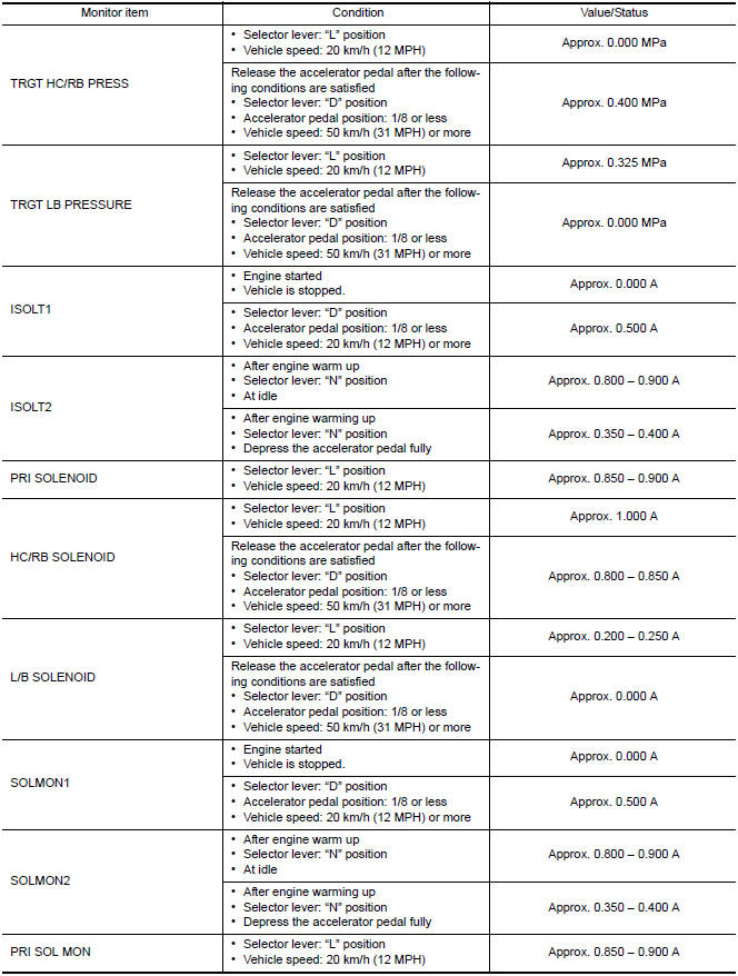
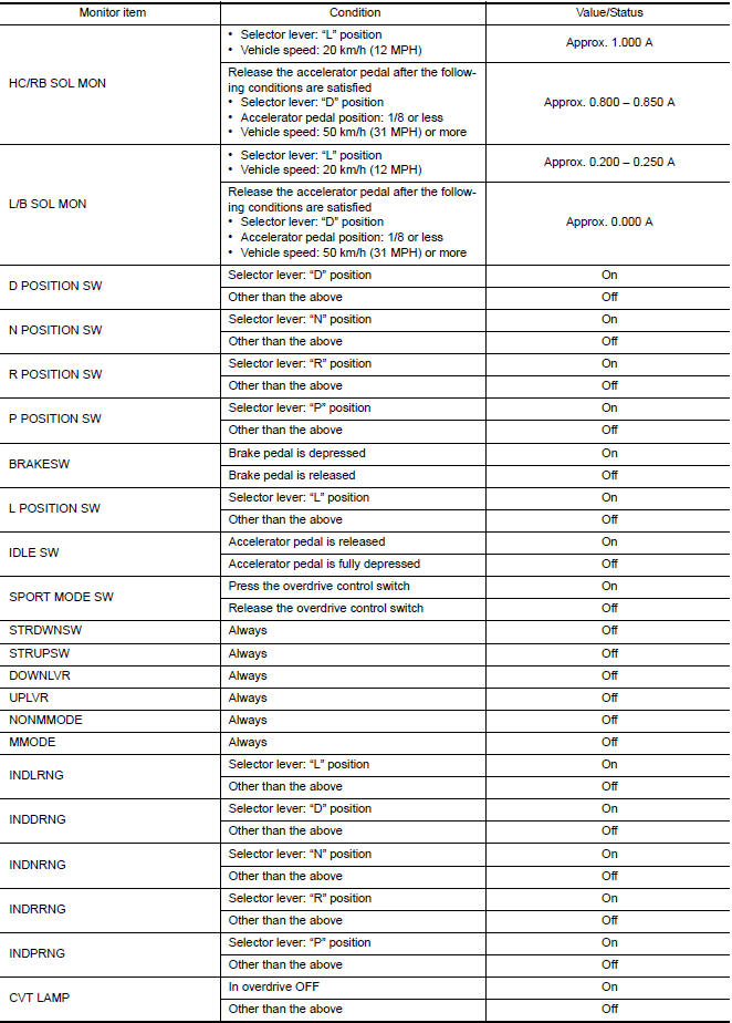
CONSULT DATA MONITOR STANDARD VALUE
- In CONSULT, electric shift timing or lock-up timing, i.e. operation
timing of each solenoid valve, is displayed.
Therefore, if there is an obvious difference between the shift timing estimated from a shift shock (or engine speed variations) and that shown on the CONSULT, the mechanism parts (including the hydraulic circuit) excluding the solenoids and sensors may be malfunctioning. In this case, check the mechanical parts following the appropriate diagnosis procedure.
- Shift point (gear position) displayed on CONSULT slightly differs from
shift pattern described in Service Manual.
This is due to the following reasons.
- Actual shift pattern may vary slightly within specified tolerances.
- While shift pattern described in Service Manual indicates start of each shift, CONSULT shows gear position at end of shift.
- The solenoid display (ON/OFF) on CONSULT is changed at the start of gear shifting. In contrast, the gear position display is changed at the time when gear shifting calculated in the control unit is completed.
NOTE: The following table includes information (items) inapplicable to this vehicle. For information (items) applicable to this vehicle, refer to CONSULT display items.
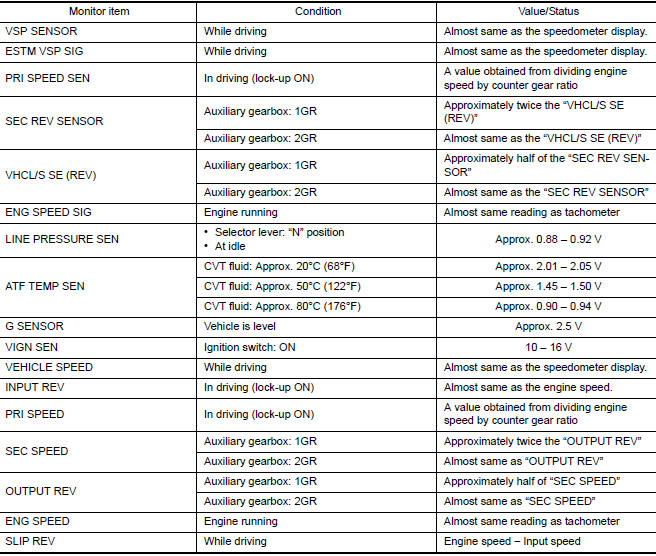
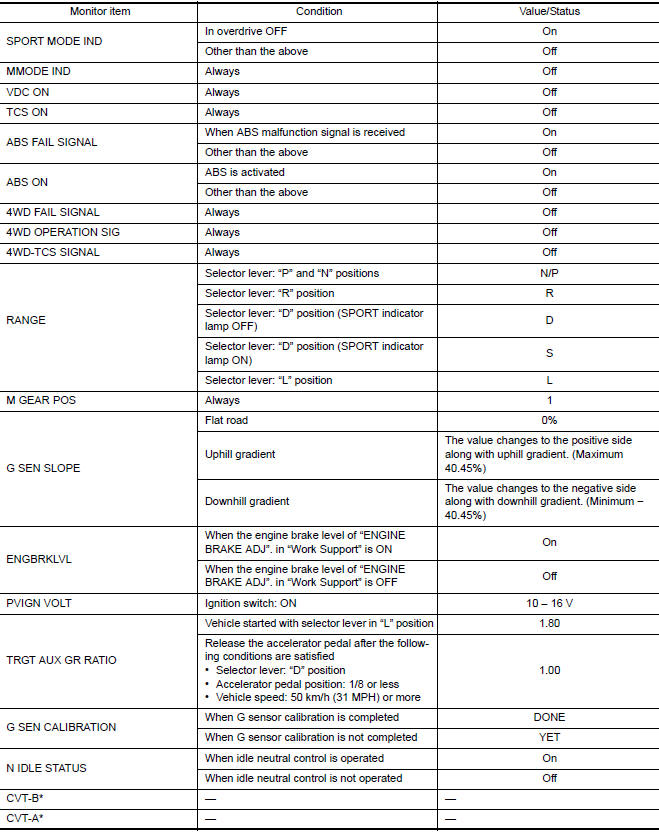
*: These monitor items do not use.
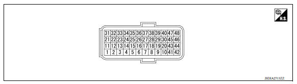
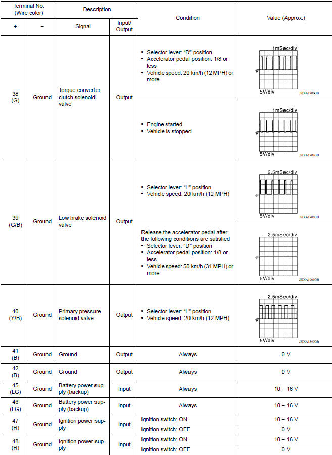
TERMINAL LAYOUT
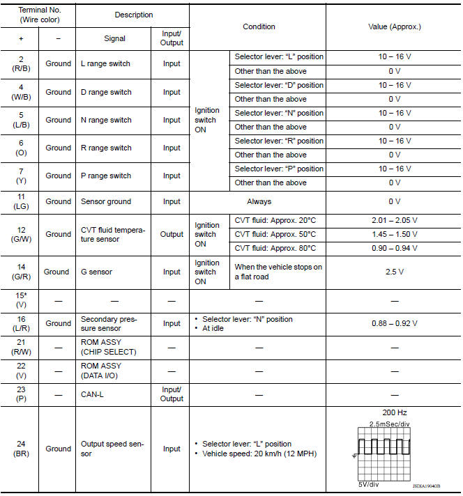
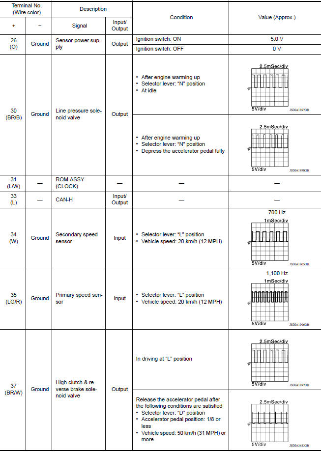
INPUT/OUTPUT SIGNAL STANDARD
Fail-safe
TCM has a fail-safe mode. The mode functions so that operation can be continued even if the signal circuit of the main electronically controlled input/output parts is damaged.
If the vehicle shows following behaviors including "poor acceleration", a malfunction of the applicable system is detected by TCM and the vehicle may be in a fail-safe mode. At this time, check the DTC code and perform inspection and repair according to the malfunction diagnosis procedures.
Fail-safe function
Protection Control
The TCM becomes the protection control status temporarily to protect the safety when the safety of TCM and transmission is lost. It automatically returns to the normal status if the safety is secured.
The TCM has the following protection control.
CONTROL FOR WHEEL SPIN 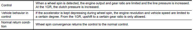
CONTROL WHEN FLUID TEMPERATURE IS HIGH 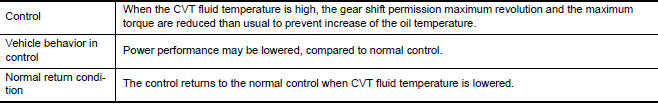
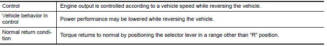
TORQUE IS REDUCED WHEN DRIVING WITH THE REVERSE GEAR
REVERSE PROHIBIT CONTROL 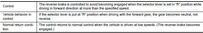
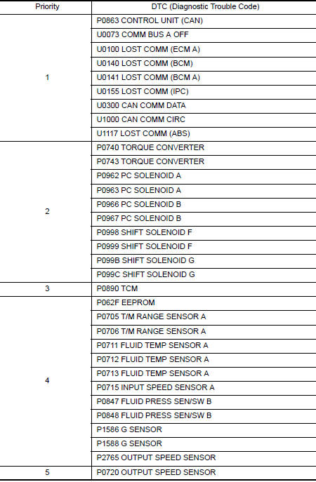
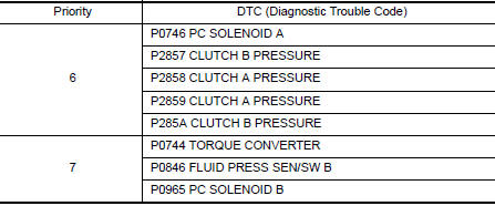
DTC Inspection Priority Chart
If multiple malfunction codes are detected at the same time, check each code according to the DTC check priority list below.
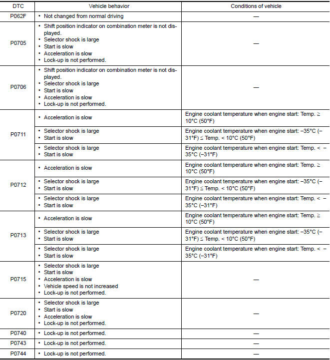
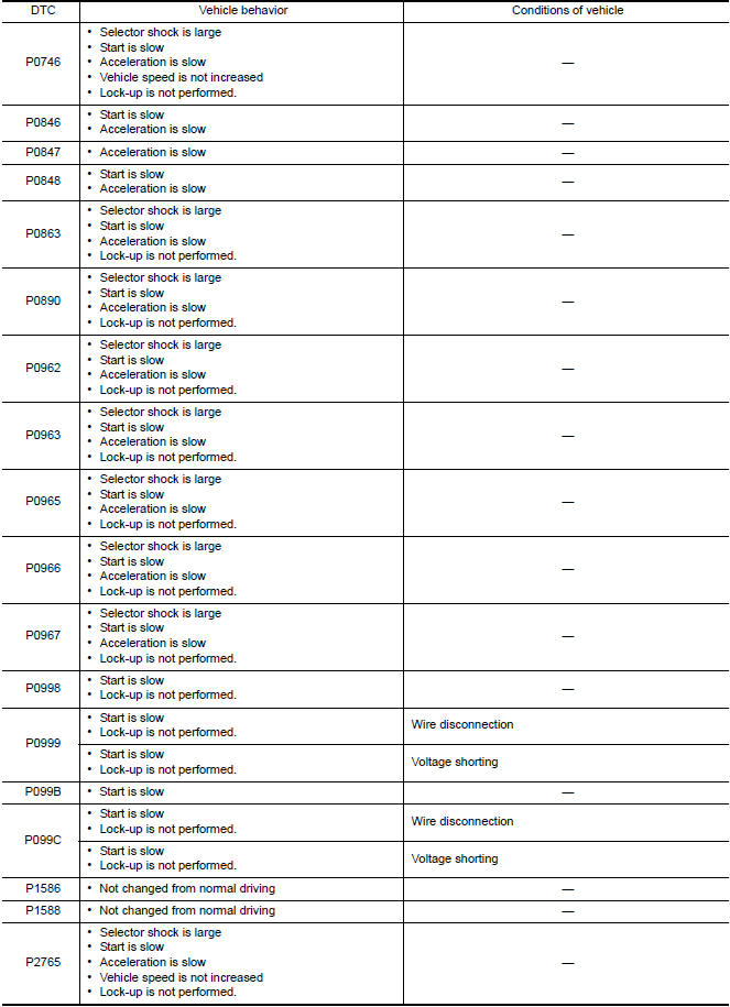
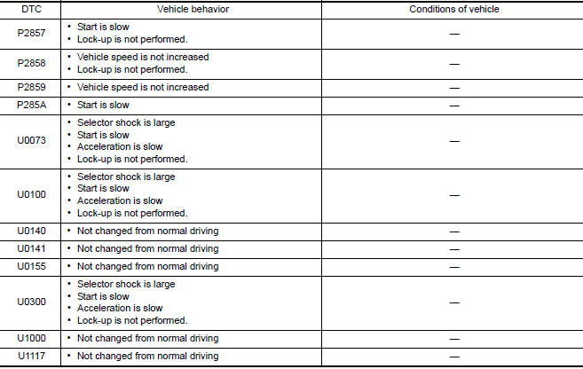
DTC Index
NOTE:
- If multiple malfunction codes are detected at the same time, check each code according to the "DTC check priority list". TM "DTC Inspection Priority Chart".
- The ignition counter is displayed in "FFD". Refer to TM "CONSULT Function".
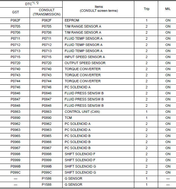
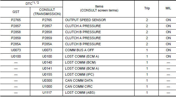
*1: These numbers are specified by SAE J2012/ISO 15031-6.
*2: The DTC number of the 1st trip is the same as the DTC number.
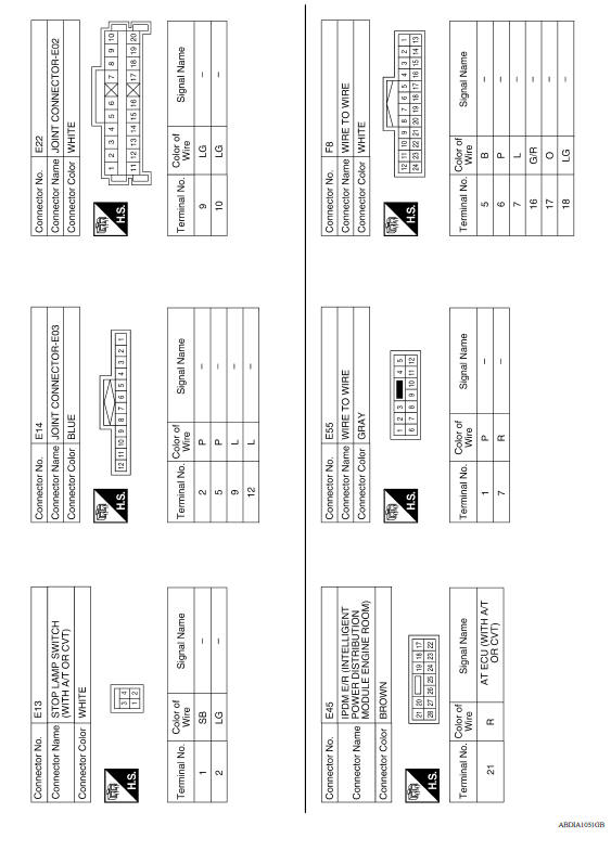
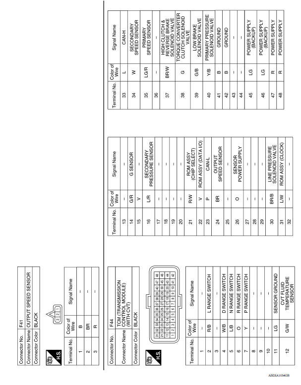
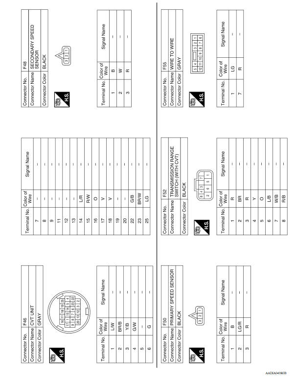
WIRING DIAGRAM
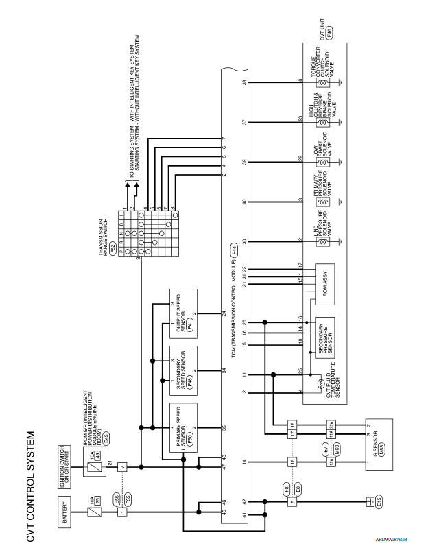
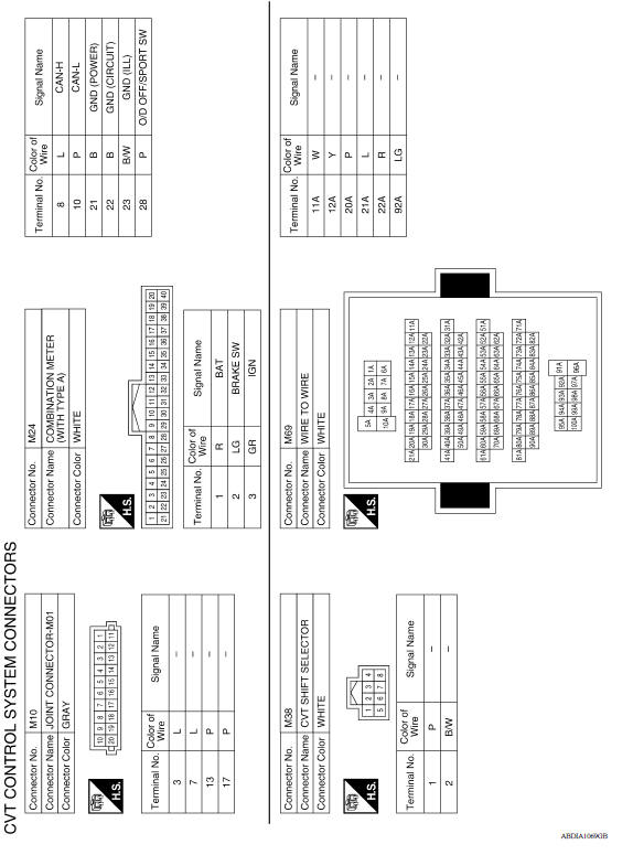
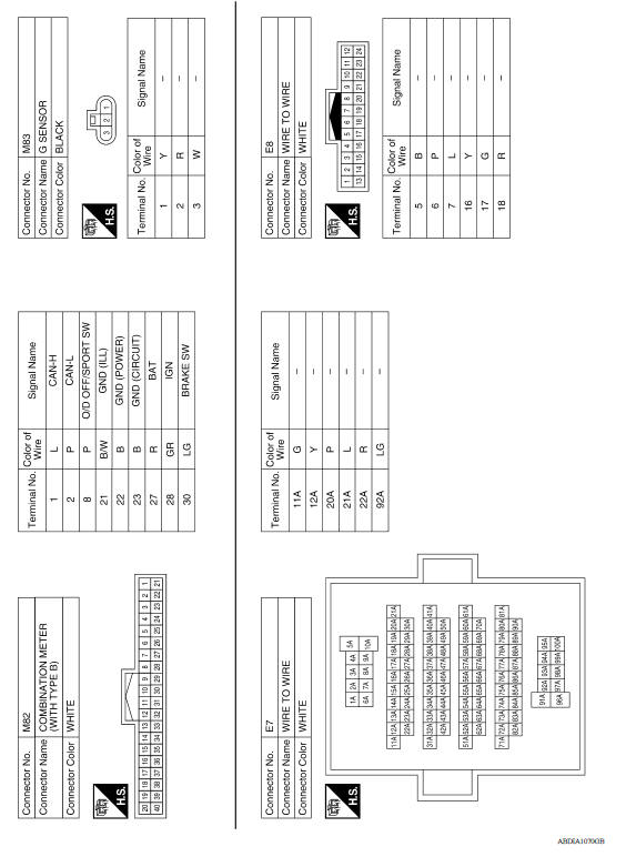
CVT CONTROL SYSTEM
Wiring Diagram
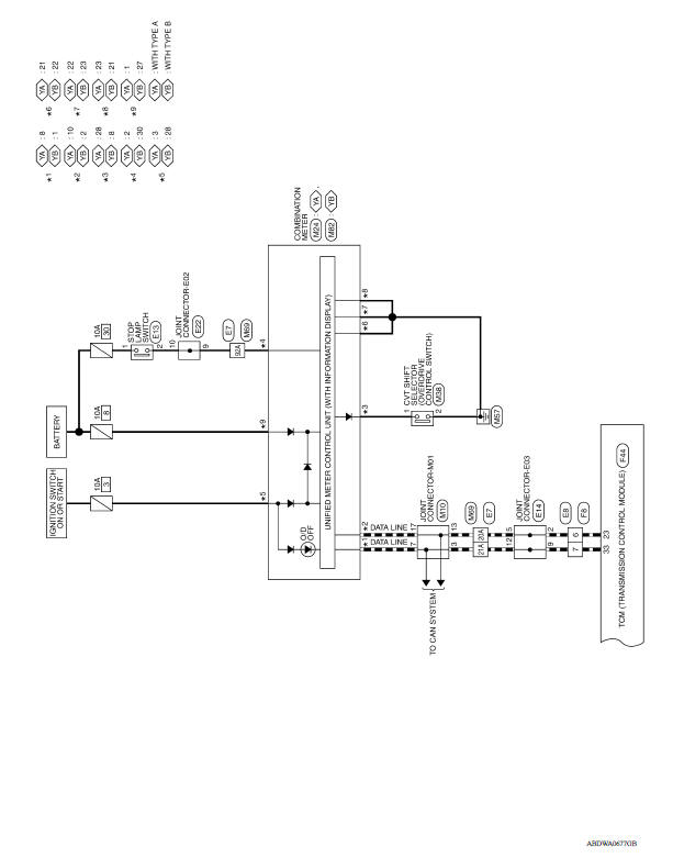
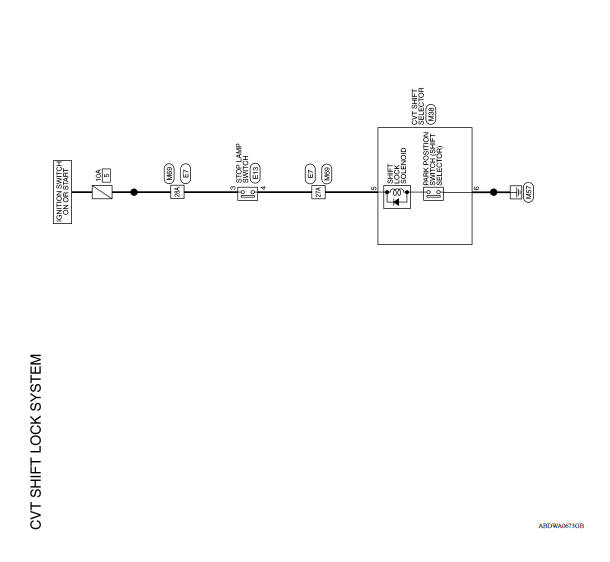
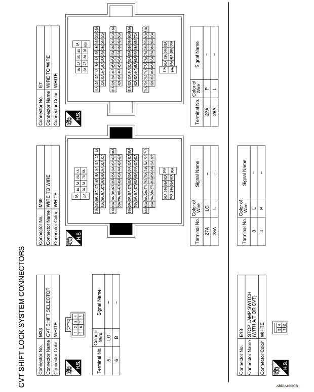
CVT SHIFT LOCK SYSTEM
Wiring Diagram
 Diagnosis system (TCM)
DIAGNOSIS DESCRIPTION ...

Other materials:
P1212 TCS communication line
Description
This CAN communication line is used to control the smooth engine operation
during the TCS operation. Pulse
signals are exchanged between ECM and "ABS actuator and electric unit (control
unit)".
Be sure to erase the malfunction information such as DTC not only for "ABS
actuat ...
Removal and installation
ECM
Exploded View
1. ECM bracket 2. ECM
: Vehicle front
Removal and Installation
CAUTION: Perform ADDITIONAL SERVICE WHEN REPLACING ECM. Refer to
EC-122, "Work Procedure".
REMOVAL
Remove battery. Refer to PG, "Removal and Installation".
Remove IPDM E/R. Re ...
Categories
- Manuals Home
- Nissan Versa Owners Manual
- Nissan Versa Service Manual
- Video Guides
- Questions & Answers
- External Resources
- Latest Updates
- Most Popular
- Sitemap
- Search the site
- Privacy Policy
- Contact Us

0.005