Nissan Versa (N17): Transmitter
Exploded View
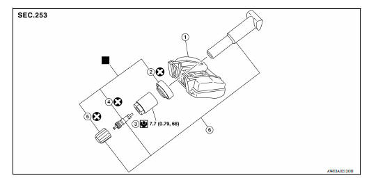
1. Transmitter (tire pressure sensor) 2. O-ring 3. Valve stem nut
4. Valve core 5. Valve cap 6. Valve stem assembly
 : Parts that are replaced as a set
when the tire is replaced.
: Parts that are replaced as a set
when the tire is replaced.
Removal and Installation
REMOVAL
- Remove road wheel and tire assembly using power tool. Refer to WT "Adjustment".
- Remove valve cap and valve core to deflate the tire.
NOTE: If the tire is to be reused, apply a matching mark on the tire in line with the position of the road wheel valve stem assembly for the purpose of road wheel and tire balance adjustment after installation.
- Remove the valve stem nut and allow transmitter to fall into tire.
- Lubricate the tire outside bead well with a suitable non-silicone lubricant, and remove outside of tire from the road wheel. Reach inside the tire and remove the transmitter.
CAUTION:
- Do not use silicone lubricant. Use of silicone lubricant will deteriorate the tire and road wheel.
- Be sure not to damage the road wheel or transmitter.
- Do not allow lubricant to make contact with transmitter.
- Lubricate the tire inside bead well with a suitable non-silicone lubricant, and remove inside of tire from the road wheel.
CAUTION:
- Do not use silicone lubricant. Use of silicone lubricant will deteriorate the tire and road wheel.
- Be sure not to damage the road wheel.
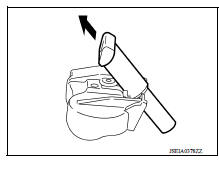
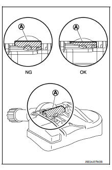
- Remove the valve stem from the transmitter as shown.
INSTALLATION
- Apply a suitable non-silicone lubricant to the tire inside bead.
CAUTION: Do not use silicone lubricant. Use of silicone lubricant will deteriorate the tire and wheel.
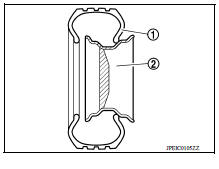
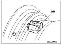
- Install the tire inside bead (1) onto the road wheel (2) in the position shown.
- Install the valve stem to the transmitter.
- Install the O-ring to the transmitter.
CAUTION:
- Do not reuse O-ring.
- Insert O-ring to the base of the transmitter.
- The base of the valve stem (A) must be positioned in the groove of the metal plate as shown.
5. Install transmitter (1) to road wheel while pressing at position (A).
CAUTION:
- Check that O-ring contacts horizontally with road wheel.
- Check that the base of the valve stem is positioned in the groove of the metal plate.
6. Install and tighten the valve stem nut to the specified torque.
Valve stem nut tightening torque : 7.7 N*m (0.79 kg-m, 68 in-lb)
CAUTION: Do not use power tool for installation.
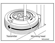
7. Place wheel on turntable of tire machine. Ensure that transmitter is 270 degrees from mounting/dismounting head. NOTE: Do not touch transmitter with mounting head.
8. Apply a suitable non-silicone lubricant to the tire outside bead.
CAUTION:
- Do not use silicone lubricant. Use of silicone lubricant will deteriorate the tire and wheel.
- Do not allow lubricant to make contact with transmitter.
9. Install the tire outside bead onto the road wheel as normal. NOTE: If the tire is being reused, align the matching mark applied on the tire with the position of the road wheel valve stem assembly for the purpose of road wheel and tire balance adjustment after installation. Ensure that the tire does not rotate relative to road wheel.
10. Install the valve core and inflate tire. CAUTION: Do not reuse valve core.
11. Install the valve cap. CAUTION: Do not reuse valve cap.
12. Balance the road wheel and tire assembly. Refer to WT "Adjustment".
13. Install road wheel and tire assembly in appropriate wheel position on vehicle. Refer to WT "Adjustment".
NOTE: If replacing the transmitter, then transmitter wake up operation must be performed. Refer to WT "Work Procedure".
14. Adjust neutral position of steering angle sensor. Refer to BRC "Work Procedure".
TIRE PRESSURE RECEIVER
Removal and Installation
The tire pressure receiver is integral to the remote keyless entry receiver. Refer to DLK "Removal and Installation"(WITH INTELLIGENT KEY SYSTEM) or DLK "Removal and Installation" (WITHOUT INTELLIGENT KEY SYSTEM).
SERVICE DATA AND SPECIFICATIONS (SDS)
Road Wheel
ALUMINUM WHEEL 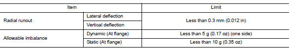
STEEL WHEEL 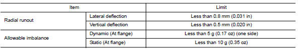
Tire Air Pressure
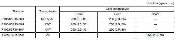
 Road wheel tire assembly
Adjustment BALANCING WHEELS (ADHESIVE WEIGHT TYPE) Preparation Before Adjustment Remove inner and outer balance weights from the road wheel. Using releasing agent, remove double-faced adhesive ...

Other materials:
EVAP leak check
Inspection
CAUTION:
Do not use compressed air or a high pressure pump.
Do not exceed 4.12 kPa (0.042 kg/cm2, 0.6 psi) of pressure in EVAP
system.
NOTE:
Do not start engine.
Improper installation of EVAP service port adapter [commercial
service tool: (J-41413-OBD)] to the EVAP ...
CVT Fluid cooler system
Cleaning
Whenever an automatic transaxle is repaired, overhauled, or replaced, the CVT
fluid cooler mounted in the
radiator must be inspected and cleaned.
Metal debris and friction material, if present, can be trapped or be deposited
in the CVT fluid cooler. This
debris can contaminate th ...
Categories
- Manuals Home
- Nissan Versa Owners Manual
- Nissan Versa Service Manual
- Video Guides
- Questions & Answers
- External Resources
- Latest Updates
- Most Popular
- Sitemap
- Search the site
- Privacy Policy
- Contact Us

0.0072