Nissan Versa (N17): Trunk lid opener cable
TRUNK LID OPENER CABLE : Removal and Installation
REMOVAL
1. Remove trunk lid striker. Refer to DLK "TRUNK LID STRIKER : Removal and Installation".
2. Remove trunk side finisher (LH). Refer to INT "TRUNK SIDE FINISHER : Removal and Installation".
3. Remove rear seat cushion. Refer to SE "Removal and Installation - Seat Cushion Assembly".
4. Remove center pillar lower finisher (LH). Refer to INT"CENTER PILLAR LOWER FINISHER : Removal and Installation".
5. Remove trunk lid opener handle. Refer to DLK "TRUNK LID OPENER HANDLE : Removal and Installation".
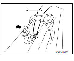
6. Release pawl using a suitable tool (A) and open the harness clip.
 Pawl
Pawl
7. Remove trunk lid opener cable.
CAUTION: Use care not to damage the trunk lid opener cable when removing.
INSTALLATION
Installation is in the reverse order of removal.
CAUTION: After installation, perform the trunk lid adjustment procedure. Refer to DLK "TRUNK LID ASSEMBLY : Adjustment".
EMERGENCY LEVER
EMERGENCY LEVER : Removal and Installation
Removal
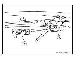
1. Release the pawls using a suitable tool and remove emergency release handle (1) from trunk lid assembly.
 Pawl
Pawl
2. Disconnect emergency release handle cable (2) from trunk lid lock assembly (3).
FUEL FILLER LID OPENER
Exploded View
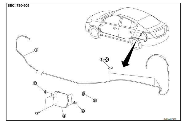
1. Fuel filler lid opener cable 2. Spring 3. Fuel filler lid assembly
4. Bumper rubber 5. Fuel filler lid lock assembly 6. Cable protector
 Clip
Clip
 Trunk lid opener handle
TRUNK LID OPENER HANDLE : Removal and Installation REMOVAL 1. Remove front kicking plate (LH). Refer to INT "KICKING PLATE INNER : Removal and Installation". 2. Release pawl using a sui ...
Fuel filler lid
FUEL FILLER LID : Removal and Installation REMOVAL 1. Fully open fuel filler lid. 2. Remove fuel cap pin (1). 3. Remove fuel filler lid screws and fuel filler lid. INSTALLATION Installation is ...
Other materials:
Idle air volume learning
Description
Idle Air Volume Learning is a function of ECM to learn the idle air volume
that keeps each engine idle speed
within the specific range. It must be performed under any of the following
conditions:
Each time electric throttle control actuator or ECM is replaced.
Idle speed or ...
Mode door cable
MODE DOOR CABLE : Removal and Installation
REMOVAL
Remove A/C unit assembly. Refer to HA "Removal and Installation".
Disconnect mode door cable from A/C control.
Disconnect mode door cable from A/C unit assembly, and then remove mode
door cable.
INSTALLATION
Installation ...
Categories
- Manuals Home
- Nissan Versa Owners Manual
- Nissan Versa Service Manual
- Video Guides
- Questions & Answers
- External Resources
- Latest Updates
- Most Popular
- Sitemap
- Search the site
- Privacy Policy
- Contact Us

0.0048