Nissan Versa (N17): U1000 CAN Comm circuit
Description
CAN (Controller Area Network) is a serial communication line for real time application. It is an on-vehicle multiplex communication line with high data communication speed and excellent error detection ability. Many electronic control units are equipped onto a vehicle, and each control unit shares information and links with other control units during operation (not independent). In CAN communication, control units are connected with 2 communication lines (CAN-H line, CAN-L line) allowing a high rate of information transmission with less wiring.
Each control unit communicate data but selectively reads required data only.
DTC Logic
DTC DETECTION LOGIC
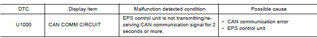
DTC CONFIRMATION PROCEDURE
1.PRECONDITIONING
If "DTC CONFIRMATION PROCEDURE" has been previously conducted, always turn ignition switch OFF and wait at least 10 seconds before conducting the next test.
>> GO TO 2.
2.DTC REPRODUCTION PROCEDURE
With CONSULT
- Turn the ignition switch OFF to ON.
- Perform "EPS" self-diagnosis.
Is DTC "U1000" detected?
YES >> Proceed to diagnosis procedure. Refer to STC "Diagnosis Procedure".
NO >> Inspection End.
Diagnosis Procedure
Proceed to LAN "Trouble Diagnosis Flow Chart".
 C1610 Engine status signal
Description EPS control unit receives the engine status signal from ECM via CAN communication line. ...
EPS Warning lamp
Component Function Check 1.CHECK THE ILLUMINATION OF THE EPS WARNING LAMP Check that the EPS warning lamp turns ON when ignition switch turns ON. Then, EPS warning lamp turns OFF after the engin ...
Other materials:
Service data and specifications
(sds)
General Specification
GENERAL SPECIFICATIONS
Engine type
HR16DE
Cylinder arrangement
Inline 4
Displacement &nbs ...
P1148 closed loop control
DTC Logic
DTC DETECTION LOGIC
NOTE:
DTC P1148 is displayed with DTC for A/F sensor 1.
When the DTC is detected, perform the trouble diagnosis of DTC corresponding to
A/F sensor 1.
DTC No.
Trouble diagnosis
(Trouble diagnosis content)
DTC detecting condition
Possible cause ...
Categories
- Manuals Home
- Nissan Versa Owners Manual
- Nissan Versa Service Manual
- Video Guides
- Questions & Answers
- External Resources
- Latest Updates
- Most Popular
- Sitemap
- Search the site
- Privacy Policy
- Contact Us

0.0051