Nissan Versa (N17): U1000 CAN Comm circuit
Description
Refer to LAN"CAN COMMUNICATION SYSTEM : System Description".
DTC Logic
DTC DETECTION LOGIC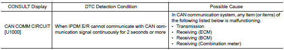
Diagnosis Procedure
1. PERFORM SELF DIAGNOSTIC RESULT
1. Turn ignition switch ON and wait for 2 second or more.
2. Check "SELF-DIAG RESULTS" of IPDM E/R.
Is "CAN COMM CIRCUIT" displayed?
YES >> Refer to LAN "Trouble Diagnosis Flow Chart".
NO >> Refer to GI "Intermittent Incident".
 IPDM E/R (Intelligent power distribution
module engine room)
IPDM E/R (Intelligent power distribution
module engine room)
Reference Value VALUES ON THE DIAGNOSIS TOOL TERMINAL LAYOUT PHYSICAL VALUES Fail-safe CAN COMMUNICATION CONTROL When CAN communication with ECM and BCM is impossible ...
B2098 Ignition relay on stuck
Description IPDM E/R operates the ignition relay when it receives an ignition switch ON signal from BCM via CAN communication. Turn the ignition relay OFF by pressing the push-button igniti ...
Other materials:
Air cleaner and air duct
Exploded View
1. Clamp 2. PCV hose 3. Clamp
4. Mount rubber 5. Air duct (inlet) 6. Air cleaner body
7. Grommet 8. Air cleaner filter 9. Air cleaner cover
10. Mass air flow sensor 11. Air duct 12. Clamp
Removal and Installation
REMOVAL
NOTE:
Mass air flow sensor is removable as an assemb ...
Automatic speed control device (ASCD)
Automatic speed control device (ascd) : system diagram
NOTE:
Transmission range switch and TCM is also for A/T models.
Automatic speed control device (ascd) : system description
INPUT/OUTPUT SIGNAL CHART
Sensor
Input signal to ECM
ECM function
Actuator
Brake pedal ...
Categories
- Manuals Home
- Nissan Versa Owners Manual
- Nissan Versa Service Manual
- Video Guides
- Questions & Answers
- External Resources
- Latest Updates
- Most Popular
- Sitemap
- Search the site
- Privacy Policy
- Contact Us

0.0057