Nissan Versa (N17): U1000 CAN Comm circuit
Description
Refer to LAN "CAN COMMUNICATION SYSTEM : System Description".
DTC Logic
DTC DETECTION LOGIC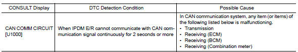
Diagnosis Procedure
1. PERFORM SELF DIAGNOSTIC RESULT
1. Turn ignition switch ON and wait for 2 second or more.
2. Check "SELF-DIAG RESULTS" of IPDM E/R.
Is "CAN COMM CIRCUIT" displayed?
YES >> Refer to LAN "Trouble Diagnosis Flow Chart".
NO >> Refer to GI "Intermittent Incident".
 IPDM E/R (Intelligent power distribution
module engine room)
IPDM E/R (Intelligent power distribution
module engine room)
Reference Value VALUES ON THE DIAGNOSIS TOOL TERMINAL LAYOUT PHYSICAL VALUES *:M/T **:CVT or A/T ...
B2098 Ignition relay on stuck
Description The ignition relay integrated in IPDM E/R is operated with ignition switch ON signal from the ignition switch. DTC Logic DTC DETECTION LOGIC Diagnosis Procedure 1. PERFORM SELF ...
Other materials:
When traveling or registering in another country
When planning to drive your NISSAN vehicle
in another country, you should first find
out if the fuel available is suitable for your vehicle's
engine.
Using fuel with an octane rating that is too low
may cause engine damage. All gasoline vehicles
must be operated with unleaded gasoline. There ...
Rear oil seal
REAR OIL SEAL : Removal and Installation
REMOVAL
Remove transaxle assembly.
Remove clutch cover and clutch disk (M/T models).
Remove flywheel (M/T models) or drive plate (A/T or CVT models).
Remove rear oil seal with a suitable tool.
CAUTION:
Be careful not to damage crankshaft an ...
Categories
- Manuals Home
- Nissan Versa Owners Manual
- Nissan Versa Service Manual
- Video Guides
- Questions & Answers
- External Resources
- Latest Updates
- Most Popular
- Sitemap
- Search the site
- Privacy Policy
- Contact Us

0.0061