Nissan Versa (N17): B2098 Ignition relay on stuck
Description
The ignition relay integrated in IPDM E/R is operated with ignition switch ON signal from the ignition switch.
DTC Logic
DTC DETECTION LOGIC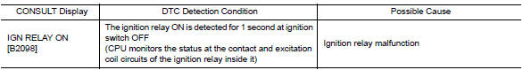
Diagnosis Procedure
1. PERFORM SELF DIAGNOSTIC RESULT
1. Turn the ignition switch ON.
2. Erase "SELF-DIAG RESULTS" of IPDM E/R.
3. Turn ignition switch OFF, and wait for 1 second or more.
4. Turn the ignition switch ON. Check "SELF-DIAG RESULTS" again.
Is "IGN RELAY ON" displayed?
YES >> Replace IPDM E/R. Refer to PCS "Removal and Installation".
NO >> Refer to GI "Intermittent Incident".
 U1000 CAN Comm circuit
Description Refer to LAN "CAN COMMUNICATION SYSTEM : System Description". DTC Logic DTC DETECTION LOGIC Diagnosis Procedure 1. PERFORM SELF DIAGNOSTIC RESULT 1. Turn ignition swi ...
B2099 Ignition relay off stuck
Description The ignition relay integrated in IPDM E/R is operated with ignition switch ON signal from the ignition switch. DTC Logic DTC DETECTION LOGIC Diagnosis Procedure 1. PERFORM SELF ...
Other materials:
Shift position indicator circuit
Component Parts Function Inspection
1.CHECK SHIFT POSITION INDICATOR
Start the engine.
Shift selector lever.
Check that the selector lever position and the shift position indicator
on the combination meter are identical.
Is the inspection result normal?
YES >> INSPECTION END
N ...
Front drive shaft
Exploded View
1. Circlip 2. Dust shield 3. Slide joint housing
4. Snap ring 5. Spider assembly 6. Boot band
7. Boot 8. Shaft 9. Damper band
10. Dynamic damper 11. Circlip 12. Joint sub-assembly
Wheel side
Disassembly and Assembly
DISASSEMBLY
Transaxle Side
Fix shaft with a vise.
...
Categories
- Manuals Home
- Nissan Versa Owners Manual
- Nissan Versa Service Manual
- Video Guides
- Questions & Answers
- External Resources
- Latest Updates
- Most Popular
- Sitemap
- Search the site
- Privacy Policy
- Contact Us

0.0059