Nissan Versa (N17): P0846 Transmission fluid pressure SEN/SW B
DTC Logic
DTC DETECTION LOGIC
| DTC | Trouble diagnosis name | DTC detection condition | Possible causes |
| P0846 | Transmission Fluid Pressure Sensor/Switch B Circuit Range/Performance | The detection conditions continuously for 5
seconds or more under the following diagnosis
conditions: - Diagnosis conditions - Selector lever: "D" position - The primary pulley speed experienced 306 rpm or more and the secondary pulley speed experienced 230 rpm or more at least once. - Wheel spin is not being detected. - The rate of change in pulley ratio: Between −0.09 and +0.09 inclusive - Solenoid valve output current: 750 mA or more - GND short diagnosis of the solenoid valve circuit is not satisfied. - TCM power supply voltage: More than 11 V - Detection conditions - After the value of "Actual secondary pressure − Target secondary pressure" exceeds 0.675 MPa: - The rate of change in vehicle speed [km/h (MPH)]: Between −49 (−30) and +49 (+30) inclusive - The rate of change in accelerator pedal angle: Between −1.3/8 and +1.3/8 inclusive |
- Secondary pressure sensor - Control valve assembly |
CAUTION: Be careful of the driving speed.
1.PREPARATION BEFORE WORK
If another "DTC CONFIRMATION PROCEDURE" occurs just before, turn ignition switch OFF and wait for at least 10 seconds, then perform the next test.
>> GO TO 2.
2.CHECK DTC DETECTION
- Start the engine.
- Shift the selector lever to "D" position.
- Drive the vehicle at a constant velocity of 40 km/h (25 MPH) at lease
for 10 seconds.
CAUTION: At the same time, the accelerator pedal angle must be maintained constant.
- Stop the vehicle.
- Check the first trip DTC.
Is "P0846"detected?
YES >> Go to TM "Diagnosis Procedure".
NO >> INSPECTION END
Diagnosis Procedure
1.CHECK TCM INPUT SIGNAL
- Start the engine.
- Check voltage between TCM connector terminal and ground.
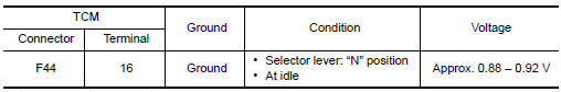
Is the inspection result normal?
YES >> Check intermittent incident. Refer to GI "Intermittent Incident".
NO >> There is a malfunction of secondary pressure sensor value. Replace transaxle assembly. Refer to TM "Removal and Installation".
 P0746 Pressure control solenoid A
Other materials:
P0705 Transmission range switch A
DTC Logic
DTC DETECTION LOGIC
DTC
Trouble diagnosis name
DTC detection condition
Possible causes
P0705
Transmission Range Sensor
"A" Circuit Malfunction (PRNDL
input)
The following diagnosis conditions
are met and 2 or more position
signals are ON at the
...
Rear pillar finisher
REAR PILLAR FINISHER : Removal and Installation
REMOVAL
Partially remove rear body side welt. Refer to INT "BODY SIDE WELT :
Removal and Installation".
Remove rear seat cushion. Refer to SE "Removal and Installation - Seat
Cushion Assembly".
Remove the rear seat bo ...
Categories
- Manuals Home
- Nissan Versa Owners Manual
- Nissan Versa Service Manual
- Video Guides
- Questions & Answers
- External Resources
- Latest Updates
- Most Popular
- Sitemap
- Search the site
- Privacy Policy
- Contact Us

0.0054