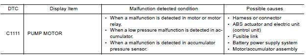
Nissan Versa (N17): C1111 Pump motor
DTC Logic
DTC DETECTION LOGIC
DTC CONFIRMATION PROCEDURE
1.CHECK SELF DIAGNOSTIC RESULT
With CONSULT.
- Turn ignition switch OFF.
- Depress brake pedal 20 times or more.
- Start the engine and wait for 3 minutes or more.
- Perform self diagnostic result.
Is DTC C1111 detected?
YES >> Proceed to diagnosis procedure. Refer to BRC "Diagnosis Procedure".
NO >> Inspection End.
Diagnosis Procedure
Regarding Wiring Diagram information, refer to BRC "Wiring Diagram".
1.CONNECTOR INSPECTION
- Turn ignition switch OFF.
- Disconnect ABS actuator and electric unit (control unit) connectors.
- Check connectors and terminals for deformation, disconnection, looseness or damage.
Is the inspection result normal?
YES >> GO TO 2
NO >> Repair or replace as necessary.
2.CHECK ABS MOTOR AND MOTOR RELAY BATTERY POWER SUPPLY
Check voltage between ABS actuator and electric unit (control unit) connector
E33 terminal 1 and ground. 
Is the inspection result normal?
YES >> GO TO 3.
NO >> Repair or replace malfunctioning components.
3.CHECK ABS ACTUATOR AND ELECTRIC UNIT (CONTROL UNIT) GROUND CIRCUIT
Check continuity between ABS actuator and electric unit (control unit)
connector E33 terminals 13, 38 and
ground.
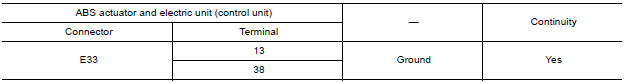
Is the inspection result normal?
YES >> Replace ABS actuator and electric unit (control unit). Refer to BRC "Removal and Installation".
NO >> Repair or replace malfunctioning components.
 C1110, C1153, C1170 ABS Actuator and
electric unit (control unit)
C1110, C1153, C1170 ABS Actuator and
electric unit (control unit)
DTC Logic DTC DETECTION LOGIC DTC CONFIRMATION PROCEDURE 1.CHECK SELF-DIAGNOSIS RESULTS Check the self-diagnosis results. ...

Other materials:
If your vehicle overheats
If your vehicle is overheating (indicated by an
extremely high temperature gauge reading (if so
equipped), a red high temperature warning light
(if so equipped) ), or if you feel a
lack of
engine power, detect abnormal noise, etc. take
the following steps.
WARNING
Do not continue to driv ...
A/T Fluid cooler
Cleaning
Whenever the A/T is repaired, overhauled, or replaced, the A/T fluid cooler
mounted in the radiator must be
inspected and cleaned.
Metal debris and friction material, if present, can become trapped in the A/T
fluid cooler. This debris can contaminate
the newly serviced A/T or, i ...
Categories
- Manuals Home
- Nissan Versa Owners Manual
- Nissan Versa Service Manual
- Video Guides
- Questions & Answers
- External Resources
- Latest Updates
- Most Popular
- Sitemap
- Search the site
- Privacy Policy
- Contact Us

0.0069