Nissan Versa (N17): Brake pedal
Exploded View
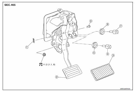
1. Clevis pin 2. Brake pedal assembly 3. Brake pedal pad 4. Stop lamp switch 5. Clip 6. Snap pin 7. ASCD cancel switch (if equipped)
NOTE: CVT and A/T brake pedal assemblies shown, M/T brake pedal assembly similar.
Removal and Installation
REMOVAL
- Remove instrument lower panel LH. Refer to IP "Removal and Installation".
- Disconnect the harness connectors from the stop lamp switch and ASCD cancel switch (if equipped).
- Disconnect the harness connector from the accelerator pedal.
- Separate the harness from brake pedal assembly.
- Rotate the stop lamp switch counter clockwise to remove.
- Rotate the ASCD cancel switch counter clockwise to remove (if equipped).
- Remove snap pin and clevis pin from clevis.
CAUTION: Do not reuse the snap pin and clevis pin.
- Disconnect the power steering harness connector and position it aside.
- Remove the brake pedal assembly.
CAUTION: Hold the brake booster and master cylinder assembly so as not to drop out or contact them other parts.
- Disconnect accelerator pedal from brake pedal assembly. Refer to ACC "Exploded View".
- Perform inspection after removal. Refer to BR "Inspection and Adjustment".
INSTALLATION
Note the following, and install in the reverse order of removal.
CAUTION: Do not reuse the snap pin and clevis pin.
- Apply the multi-purpose grease to the clevis pin and the mating faces. (Not necessary if grease has been already applied)
NOTE:
- The clevis pin may be inserted in either direction.
- Do not give any impact caused by dropping, interference with a tool, contact between parts or with rack to the brake pedal.
- Do not use an part that has been subject to an impact.
- Perform adjustment after installation. Refer to BR "Inspection and Adjustment".
Inspection and Adjustment
INSPECTION AFTER REMOVAL
- Check the brake pedal for bend, damage, and cracks on the welded parts, and replace the brake pedal assembly if necessary.
ADJUSTMENT AFTER INSTALLATION
- Adjust each item of brake pedal after installing the brake pedal assembly to the vehicle. Refer to BR "Inspection and Adjustment".
- Perform the release position learning of the accelerator pedal. Refer to EC "Work Procedure".
BRAKE PIPING
 Brake drum
BRAKE DRUM : Inspection and Adjustment INSPECTION Appearance Check surface of brake drum for uneven wear, cracks and serious damage. Replace it if necessary. Refer to BR "Removal and Instal ...
Front
FRONT : Exploded View 1. Master cylinder brake pipe assembly (front) 2. Master cylinder brake pipe assembly (rear) 3. ABS actuator to connector brake pipe assembly (RH) 4. ABS actuator to ...
Other materials:
Break-in schedule
CAUTION
During the first 1,200 miles (2,000 km),
follow these recommendations to obtain
maximum engine performance and ensure
the future reliability and economy of your
new vehicle. Failure to follow these recommendations
may result in shortened
engine life and reduced engine
performance.
...
Multiport fuel injection system
MULTIPORT FUEL INJECTION SYSTEM : System Diagram
MULTIPORT FUEL INJECTION SYSTEM : System
Description
INPUT/OUTPUT SIGNAL CHART
Sensor
Input signal to ECM
ECM function
Actuator
Crankshaft position sensor (POS)
Engine speed*4
Piston position
Fuel injection & ...
Categories
- Manuals Home
- Nissan Versa Owners Manual
- Nissan Versa Service Manual
- Video Guides
- Questions & Answers
- External Resources
- Latest Updates
- Most Popular
- Sitemap
- Search the site
- Privacy Policy
- Contact Us

0.0058