Nissan Versa (N17): Shift lock system
Component Function Check
1.CHECK SHIFT LOCK OPERATION (BRAKE PEDAL RELEASED)
- Ignition switch ON.
- Attempt to shift selector lever to any position other than "P" position with brake pedal released.
Can the selector lever be shifted?
YES >> Go to TM "Diagnosis Procedure".
NO >> GO TO 2.
2.CHECK SHIFT LOCK OPERATION (BRAKE PEDAL APPLIED)
Attempt to shift the selector lever to any position other than "P" position with brake pedal applied.
Can the selector lever be shifted?
YES >> Inspection End.
NO >> Go to TM "Diagnosis Procedure".
Diagnosis Procedure
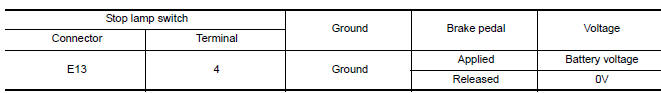
1.CHECK STOP LAMP SWITCH
- Ignition switch ON.
- Check voltage between stop lamp switch connector E13 terminal 4 and
ground.
Is the inspection result normal?
YES >> GO TO 2.
NO >> GO TO 4.
2.CHECK CVT SHIFT SELECTOR
Check voltage between CVT shift selector connector M38 terminal 6 and ground. 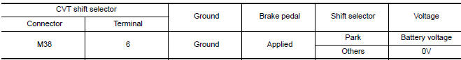
Is the inspection result normal?
YES >> GO TO 3.
NO >> GO TO 5.
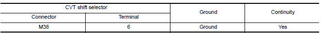
3.CHECK GROUND CIRCUIT
- Ignition switch OFF.
- Disconnect CVT shift selector connector.
- Check continuity between CVT shift selector connector M38 terminal 6 and
ground.
Is the inspection result normal?
YES >> Replace CVT shift selector. Refer to TM "Removal and Installation".
NO >> Repair or replace ground circuit.
4.CHECK STOP LAMP SWITCH POWER CIRCUIT
Check voltage between stop lamp switch connector E13 terminal 3 and ground. 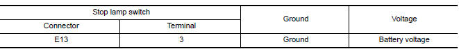
Is the inspection result normal?
YES >> Replace stop lamp switch.
NO >> Repair or replace power circuit.
5.CHECK CVT SHIFT SELECTOR POWER CIRCUIT
Check voltage between CVT shift selector connector M38 terminal 5 and ground. 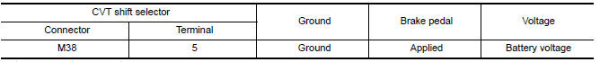
Is the inspection result normal?
YES >> Replace CVT shift selector. Refer to TM "Removal and Installation".
NO >> Repair or replace power circuit.
SYMPTOM DIAGNOSIS
 Shift position indicator circuit
Component Parts Function Inspection 1.CHECK SHIFT POSITION INDICATOR Start the engine. Shift selector lever. Check that the selector lever position and the shift position indicator on the ...
CVT Control system
Symptom Table The diagnosis item number indicates the order of check. Start checking in the order from 1. Symptom diagnosis chart 1-1 Symptom diagnosis chart 1-2 Sympto ...
Other materials:
Windshield-washer fluid
Windshield-washer fluid reservoir
Add a washer solvent to the windshield-washer
fluid reservoir for better cleaning. In the winter
season, add a windshield-washer antifreeze. Follow
the manufacturer's instructions for the mixture
ratio.
Refill the reservoir more frequently when driving
...
Intake valve timing control
Intake valve timing control : System Diagram
Intake valve timing control : system description
INPUT/OUTPUT SIGNAL CHART
Sensor
Input signal to ECM
ECM function
Actuator
Crankshaft position sensor (POS)
Engine speed*1
Piston position
Intake valve timing
con ...
Categories
- Manuals Home
- Nissan Versa Owners Manual
- Nissan Versa Service Manual
- Video Guides
- Questions & Answers
- External Resources
- Latest Updates
- Most Popular
- Sitemap
- Search the site
- Privacy Policy
- Contact Us

0.0076