Nissan Versa (N17): ABS Branch line circuit
Diagnosis Procedure
1.CHECK CONNECTOR
1. Turn the ignition switch OFF.
2. Disconnect the battery cable from the negative terminal.
3. Check the terminals and connectors of the ABS actuator and electric unit (control unit) for damage, bend and loose connection (unit side and connector side).
Is the inspection result normal?
YES >> GO TO 2.
NO >> Repair the terminal and connector.
2.CHECK HARNESS FOR OPEN CIRCUIT
1. Disconnect the connector of ABS actuator and electric unit (control unit).
2. Check the resistance between the ABS actuator and electric unit (control
unit) harness connector terminals. 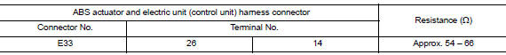
Is the measurement value within the specification?
YES >> GO TO 3.
NO >> Repair the ABS actuator and electric unit (control unit) branch line.
3.CHECK POWER SUPPLY AND GROUND CIRCUIT
Check the power supply and the ground circuit of the ABS actuator and electric unit (control unit). Refer to BRC"Diagnosis Procedure".
Is the inspection result normal?
YES (Present error)>>Replace the ABS actuator and electric unit (control unit). Refer to BRC "Removal and Installation".
YES (Past error)>>Error was detected in the ABS actuator and electric unit (control unit) branch line.
NO >> Repair the power supply and the ground circuit.
 ECM Branch line circuit
Diagnosis Procedure 1.CHECK CONNECTOR 1. Turn the ignition switch OFF. 2. Disconnect the battery cable from the negative terminal. 3. Check the terminals and connectors of the ECM for damage, bend ...
IPDM-E Branch line circuit
Diagnosis Procedure 1.CHECK CONNECTOR 1. Turn the ignition switch OFF. 2. Disconnect the battery cable from the negative terminal. 3. Check the terminals and connectors of the IPDM E/R for damag ...
Other materials:
Transmitter
Exploded View
1. Transmitter (tire pressure sensor) 2. O-ring 3. Valve stem nut
4. Valve core 5. Valve cap 6. Valve stem assembly
: Parts that are replaced as a set
when the tire is replaced.
Removal and Installation
REMOVAL
Remove road wheel and tire assembly using power tool. Refe ...
Manual air conditioning system
MANUAL AIR CONDITIONING SYSTEM : System
Diagram
MANUAL AIR CONDITIONING SYSTEM : System
Description
The manual air conditioning system is controlled by a sequence of
functions from the front air control, BCM,
ECM, and IPDM E/R.
The fan speed of the front blower motor is change ...
Categories
- Manuals Home
- Nissan Versa Owners Manual
- Nissan Versa Service Manual
- Video Guides
- Questions & Answers
- External Resources
- Latest Updates
- Most Popular
- Sitemap
- Search the site
- Privacy Policy
- Contact Us

0.0046