Nissan Versa (N17): IPDM-E Branch line circuit
Diagnosis Procedure
1.CHECK CONNECTOR
1. Turn the ignition switch OFF.
2. Disconnect the battery cable from the negative terminal.
3. Check the terminals and connectors of the IPDM E/R for damage, bend and loose connection (unit side and connector side).
Is the inspection result normal?
YES >> GO TO 2.
NO >> Repair the terminal and connector.
2.CHECK HARNESS FOR OPEN CIRCUIT
1. Disconnect the connector of IPDM E/R.
2. Check the resistance between the IPDM E/R harness connector terminals.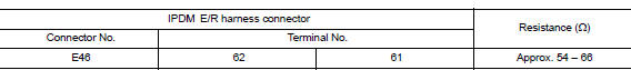
Is the measurement value within the specification?
YES >> GO TO 3.
NO >> Repair the IPDM E/R branch line.
3.CHECK POWER SUPPLY AND GROUND CIRCUIT
Check the power supply and the ground circuit of the IPDM E/R. Refer to the following.
- With Intelligent Key system: PCS "Diagnosis Procedure"
- Without Intelligent Key system: PCS "Diagnosis Procedure"
Is the inspection result normal?
YES (Present error)>>Replace the IPDM E/R. Refer to the following.
- With Intelligent Key system: PCS "Removal and Installation"
- Without Intelligent Key system: PCS "Removal and Installation"
YES (Past error)>>Error was detected in the IPDM E/R branch line.
NO >> Repair the power supply and the ground circuit.
 ABS Branch line circuit
Diagnosis Procedure 1.CHECK CONNECTOR 1. Turn the ignition switch OFF. 2. Disconnect the battery cable from the negative terminal. 3. Check the terminals and connectors of the ABS actuator and ele ...
A-BAG Branch line circuit
Diagnosis Procedure WARNING: Always observe the following items for preventing accidental activation. Before servicing, turn ignition switch OFF, disconnect battery negative terminal, and w ...
Other materials:
Preparation
Special Service Tools
The actual shapes of KentMoore tools may differ from those of special
service tools illustrated here.
Tool number
(KentMoore No.)
Tool name
Description
ST25051001
(J256951)
Oil pressure gauge &nbs ...
Precautions
Precaution for Supplemental Restraint System
(SRS) "AIR BAG" and "SEAT BELT PRE-TENSIONER"
The Supplemental Restraint System such as "AIR BAG" and "SEAT BELT PRE-TENSIONER",
used along
with a front seat belt, helps to reduce the risk or severity of injury to the
driver and ...
Categories
- Manuals Home
- Nissan Versa Owners Manual
- Nissan Versa Service Manual
- Video Guides
- Questions & Answers
- External Resources
- Latest Updates
- Most Popular
- Sitemap
- Search the site
- Privacy Policy
- Contact Us

0.0053