Nissan Versa (N17): Audio unit
Exploded View
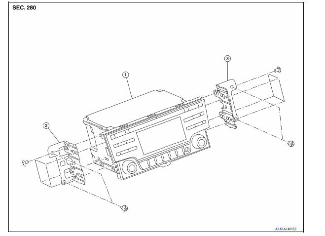
1. Audio unit 2. Audio unit bracket (LH) 3. Audio unit bracket (RH)
Removal and Installation
REMOVAL
1. Disconnect the negative battery terminal. Refer to PG "Removal and Installation".
2. Remove cluster lid C. Refer to IP "Removal and Installation".
3. Remove the audio unit screws, then pull out the audio unit.
4. Disconnect the harness connectors from the audio unit and remove.
INSTALLATION
Installation is in the reverse order of removal.
 Normal operating condition
Description RELATED TO NOISE The majority of the audio concerns are the result of outside causes (bad CD, electromagnetic interference, etc.). The following noise results from variations in fi ...
Front door speaker
Removal and Installation REMOVAL 1. Remove the front door finisher. Refer to INT "Removal and Installation". 2. Remove the front door speaker screws (A). 3. Disconnect the harness connec ...
Other materials:
Power outlets
Instrument panel
Console (if so equipped)
The power outlets are for powering electrical
accessories such as cellular telephones. The
outlets are rated at 12 volt, 120W (10A) maximum.
CAUTION
The outlet and plug may be hot during
or immediately after use.
Only certain power outlets ...
Keys
Type A (if so equipped)
1. Master key
2. Valet key
3. Key number plate
A key number plate is supplied with your keys.
Record the key number and keep it in a safe place
(such as your wallet), not in the vehicle. If you lose
your keys, it is recommended that you visit a
NISSAN dealer for ...
Categories
- Manuals Home
- Nissan Versa Owners Manual
- Nissan Versa Service Manual
- Video Guides
- Questions & Answers
- External Resources
- Latest Updates
- Most Popular
- Sitemap
- Search the site
- Privacy Policy
- Contact Us

0.0054