Nissan Versa (N17): Front door speaker
Removal and Installation
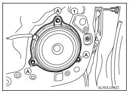
REMOVAL
1. Remove the front door finisher. Refer to INT "Removal and Installation".
2. Remove the front door speaker screws (A).
3. Disconnect the harness connector from front door speaker (1) and remove.
INSTALLATION
Installation is in the reverse order of removal.
 Audio unit
Exploded View 1. Audio unit 2. Audio unit bracket (LH) 3. Audio unit bracket (RH) Removal and Installation REMOVAL 1. Disconnect the negative battery terminal. Refer to PG "Removal an ...
Rear door speaker
Removal and Installation REMOVAL 1. Remove the rear door finisher. Refer to INT "Removal and Installation". 2. Remove the rear door speaker screws (A). 3. Disconnect the harness connec ...
Other materials:
Front suspension member
Exploded View
1. Front suspension member 2. Transverse link
Removal and Installation
REMOVAL
Remove the wheel and tire assemblies using power tool. Refer to WT
"Adjustment".
Remove transverse link. Refer to FSU-12, "Removal and Installation".
Remove steering o ...
Diagnosis system (EPS control unit)
CONSULT Function
FUNCTION
CONSULT can display each diagnostic item using the diagnostic test modes
shown following.
*: The following diagnosis information is erased by erasing.
DTC
Freeze frame data (FFD)
ECU IDENTIFICATION
Displays the part number stored in the con ...
Categories
- Manuals Home
- Nissan Versa Owners Manual
- Nissan Versa Service Manual
- Video Guides
- Questions & Answers
- External Resources
- Latest Updates
- Most Popular
- Sitemap
- Search the site
- Privacy Policy
- Contact Us

0.0048