Nissan Versa (N17): Front fender
FRONT FENDER : Removal and Installation
CAUTION: Use a shop cloths to protect the body from being damaged during removal and installation.
REMOVAL
- Remove fender protector. Refer to EXT "Removal and Installation".
- Remove front bumper fascia and bumper side bracket. Refer to EXT "Removal and Installation".
- Remove front combination lamp. Refer to EX "Removal and Installation".
- Remove front door corner finisher. Refer to MIR "FRONT DOOR CORNER FINISHER : Removal and Installation".
- Remove front fender cover. Refer to DLK "FENDER COVER : Removal and Installation".
- Remove front fender bolts from front fender.
- Remove front fender stiffener (2) while carefully pulling upper portion of front fender (1) away from body.
 : Front
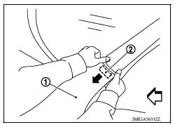
8. Remove front fender.
CAUTION:
A viscous urethane foam is installed on the back surface of front fender. When removing the front fender, be careful to not deform the front fender while performing the procedure and removing the viscous urethane foam a little at a time.
INSTALLATION
Installation is in the reverse order of removal.
CAUTION:
- Adjust the following components as necessary.
- Hood assembly: Refer to DLK "HOOD ASSEMBLY : Adjustment".
- Front door assembly: Refer to DLK "DOOR ASSEMBLY : Adjustment".
- After adjusting, apply touch-up paint (body color) onto the head of the front fender bolts.
 Radiator core support lower
RADIATOR CORE SUPPORT LOWER : Removal and Installation Removal 1. Remove under cover. Refer to EXT "Removal and Installation". 2. Remove radiator upper seal clips. 3. Remove front bumpe ...
Fender cover
FENDER COVER : Removal and Installation REMOVAL Fully open hood assembly. Disengage pawls beginning at the front of the fender cover and working toward the rear of vehicle and then remove f ...
Other materials:
Preparation
Special Service Tools
The actual shapes of KentMoore tools may differ from those of special
service tools illustrated here.
Tool number
(KentMoore No.)
Tool name
Description
ST25051001
(J256951)
Oil pressure gauge &nbs ...
Roof side molding
Exploded View
1. Roof side molding 2. Roof side molding clip 3. Roof panel
4. Body side outer panel
Removal and Installation
REMOVAL
1. Release roof side molding clip using a suitable tool (A).
: Clip
CAUTION:
Apply protective tape (B) on body to protect the painted
surface from damag ...
Categories
- Manuals Home
- Nissan Versa Owners Manual
- Nissan Versa Service Manual
- Video Guides
- Questions & Answers
- External Resources
- Latest Updates
- Most Popular
- Sitemap
- Search the site
- Privacy Policy
- Contact Us

0.006