Nissan Versa (N17): B210C Starter control relay
DTC Logic
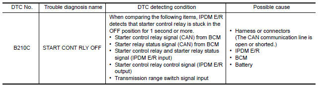
DTC DETECTION LOGIC
NOTE:
- If DTC B210C is displayed with DTC U1000, first perform the trouble diagnosis for DTC U1000. Refer to BCS "DTC Logic".
- When IPDM E/R power supply voltage is low (Approx. 7 - 8 V for about
1 second), the DTC B210C may be
detected.
DTC CONFIRMATION PROCEDURE
1.PERFORM DTC CONFIRMATION PROCEDURE
1. Press push-button ignition switch under the following conditions to start engine, and wait 1 second or more.
Selector lever: In the P position
Brake pedal: Not depressed
2. Check DTC in Self Diagnostic Result mode of IPDM E/R using CONSULT.
Is DTC detected?
YES >> Go to SEC "Diagnosis Procedure".
NO >> Inspection End.
Diagnosis Procedure
1.CHECK DTC FOR BCM
Check DTC in Self Diagnostic Result mode of BCM using CONSULT.
Is DTC detected?
YES >> Perform the trouble diagnosis related to the detected DTC. Refer to BCS "DTC Index".
NO >> GO TO 2.
2.INSPECTION START
1. Turn ignition switch ON.
2. Select Self Diagnostic Result mode of IPDM E/R using CONSULT.
3. Touch "ERASE".
4. Perform DTC CONFIRMATION PROCEDURE for DTC B210C. Refer to SEC "DTC Logic".
Is DTC detected?
YES >> GO TO 3.
NO >> Inspection End.
3.REPLACE BCM
1. Replace BCM. Refer to BCS "Removal and Installation".
2. Perform initialization of BCM and registration of all Intelligent Keys using CONSULT.
3. Perform DTC CONFIRMATION PROCEDURE for DTC B210C. Refer to SEC "DTC Logic".
Is the inspection result normal?
YES >> Inspection End.
NO >> Replace IPDM E/R. Refer to PCS "Removal and Installation".
 B210B Starter control relay
Other materials:
Head restraints/headrests
WARNING
Head restraints/headrests supplement
the other vehicle safety systems. They may
provide additional protection against injury
in certain rear end collisions. Adjustable
head restraints/headrests must be
adjusted properly, as specified in this section.
Check the adjustment after someo ...
Cleaning interior
Occasionally remove loose dust from the interior
trim, plastic parts and seats using a vacuum
cleaner or soft bristled brush. Wipe the vinyl and
leather surfaces with a clean, soft cloth dampened
in mild soap solution, then wipe clean with a
dry, soft cloth.
Regular care and cleaning is requ ...
Categories
- Manuals Home
- Nissan Versa Owners Manual
- Nissan Versa Service Manual
- Video Guides
- Questions & Answers
- External Resources
- Latest Updates
- Most Popular
- Sitemap
- Search the site
- Privacy Policy
- Contact Us

0.0059