Nissan Versa (N17): B210D Starter relay
DTC Logic
DTC DETECTION LOGIC
NOTE: If DTC B210D is displayed with DTC U1000, first perform the trouble
diagnosis for DTC U1000. Refer to BCS "DTC Logic". 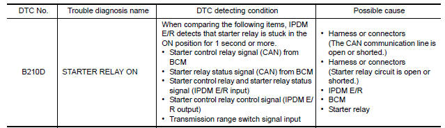
DTC CONFIRMATION PROCEDURE
1.PERFORM DTC CONFIRMATION PROCEDURE
1. Press push-button ignition switch under the following conditions to start engine, and wait 1 second or more.
- Selector lever: In the P position
- Brake pedal: Not depressed
2. Check DTC in Self Diagnostic Result mode of IPDM E/R using CONSULT.
Is DTC detected?
YES >> Go to SEC"Diagnosis Procedure".
NO >> Inspection End
Diagnosis Procedure
Regarding Wiring Diagram information, refer to SEC "Wiring Diagram".
1.CHECK STARTER RELAY POWER SUPPLY CIRCUIT
1. Turn ignition switch ON.
2. Check voltage between BCM harness connector and ground.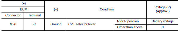
Is the inspection result normal?
YES >> GO TO 3.
NO >> GO TO 2.
2.CHECK STARTER RELAY CIRCUIT
1. Turn ignition switch OFF.
2. Disconnect starter relay.
3. Disconnect BCM connector.
4. Check continuity between starter relay harness connector and BCM harness
connector.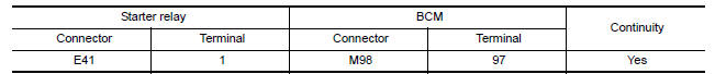
5. Check continuity between IPDM E/R harness connector and ground. 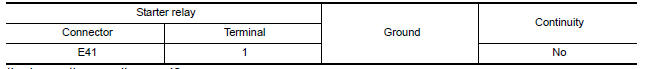
Is the inspection result normal?
YES >> Replace IPDM E/R. Refer to PCS "Removal and Installation".
NO >> Repair or replace harness.
3.CHECK STARTER RELAY
Refer to SEC "Component Inspection".
Is the inspection result normal?
YES >> GO TO 4.
NO >> Replace starter relay.
4.REPLACE BCM
1. Replace BCM. Refer to BCS "Removal and Installation".
2. Perform initialization of BCM and registration of all Intelligent keys using CONSULT.
3. Perform DTC CONFIRMATION PROCEDURE for DTC B210D. Refer to SEC "DTC Logic".
Is the inspection result normal?
YES >> Inspection End.
NO >> Replace IPDM E/R. Refer to PCS "Removal and Installation".
Component Inspection
1.CHECK STARTER RELAY
1. Turn ignition switch OFF.
2. Disconnect starter relay.
3. Check continuity between starter relay terminals. 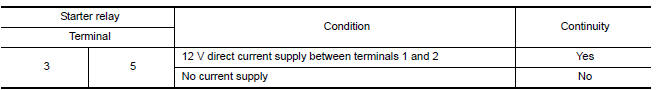
Is the inspection result normal?
YES >> Inspection End.
NO >> Replace starter relay.
 B210C Starter control relay
Other materials:
Engine assembly
Exploded View
1. Engine mounting (RH) stay 2. Engine mount (RH) stay 3. Engine mounting
insulator (RH)
4. Rear engine mounting bracket 5. Rear torque rod 6. Engine mounting bracket
(LH)
7. Engine mounting bracket (LH) 8. Engine mounting insulator (LH) 9. Mass damper
A. Front mark B. Tra ...
Control linkage
Exploded View
1. Shifter lever A 2. Selector lever 3. Selector cable
4. Shifter cable 5. Cable mounting bracket 6. Tapping bolt
7. Bracket 8. Grommet 9. M/T shift selector assembly
10. Shift selector 11. Shift selector handle
Removal and Installation
REMOVAL
Move the shift selector to ...
Categories
- Manuals Home
- Nissan Versa Owners Manual
- Nissan Versa Service Manual
- Video Guides
- Questions & Answers
- External Resources
- Latest Updates
- Most Popular
- Sitemap
- Search the site
- Privacy Policy
- Contact Us

0.0063