Nissan Versa (N17): B2110 Shift position/clutch interlock switch
DTC Logic
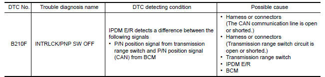
DTC DETECTION LOGIC
NOTE: If DTC B2110 is displayed with DTC U1000, first perform the trouble
diagnosis for DTC U1000. Refer to BCS "DTC Logic".
DTC CONFIRMATION PROCEDURE
1.PERFORM DTC CONFIRMATION PROCEDURE
1. Shift selector lever to the P position.
2. Turn ignition switch ON and wait 1 second or more.
3. Shift selector lever to the N position and wait 1 second or more.
4. Shift selector lever to the position other than P and N, and wait 1 second or more.
5. Check DTC in Self Diagnostic Result mode of IPDM E/R using CONSULT.
Is DTC detected?
YES >> Go to SEC "Diagnosis Procedure".
NO >> Inspection End.
Diagnosis Procedure
Regarding Wiring Diagram information, refer to SEC "Wiring Diagram".
1.CHECK DTC OF BCM
Check DTC in Self Diagnostic Result mode of BCM using CONSULT.
Is DTC detected?
YES >> Perform the trouble diagnosis related to the detected DTC. Refer to BCS-48, "DTC Index".
NO >> GO TO 2.
2.CHECK IPDM E/R SIGNAL CIRCUIT OPEN AND SHORT
1. Turn ignition switch OFF.
2. Disconnect IPDM E/R connector.
3. Disconnect transmission range switch connector.
4. Check continuity between IPDM E/R harness connector and transmission range
switch harness connector.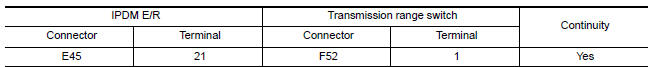
5. Check continuity between IPDM E/R harness connector and ground.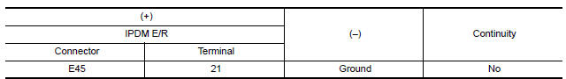
Is the inspection result normal?
YES >> Replace IPDM E/R. Refer to PCS "Removal and Installation".
NO >> Repair or replace harness.
SYMPTOM DIAGNOSIS
 B210F Shift position/clutch interlock
switch
B210F Shift position/clutch interlock
switch
Other materials:
Starting the engine (models without NISSAN Intelligent Key system)
1. Apply the parking brake.
2. Automatic Transmission / CVT models:
Move the shift lever to P (Park) or N (Neutral).
P (Park) is recommended.
The shift lever cannot be moved out of
P (Park) and into any of the other gear
positions if the ignition key is turned to
the OFF position or if ...
Air cleaner filter
Exploded View
1. Clamp 2. PCV hose 3. Clamp
4. Mount rubber 5. Air duct (inlet) 6. Air cleaner body
7. Grommet 8. Air cleaner filter 9. Air cleaner cover
10. Mass air flow sensor 11. Air duct 12. Clamp
Removal and Installation
REMOVAL
1. Unhook clips (A) and pull the air cleaner cover u ...
Categories
- Manuals Home
- Nissan Versa Owners Manual
- Nissan Versa Service Manual
- Video Guides
- Questions & Answers
- External Resources
- Latest Updates
- Most Popular
- Sitemap
- Search the site
- Privacy Policy
- Contact Us

0.0058