Nissan Versa (N17): BCM Branch line circuit
Diagnosis Procedure
1.CHECK CONNECTOR
1. Turn the ignition switch OFF.
2. Disconnect the battery cable from the negative terminal.
3. Check the terminals and connectors of the BCM for damage, bend and loose connection (unit side and connector side).
Is the inspection result normal?
YES >> GO TO 2.
NO >> Repair the terminal and connector.
2.CHECK HARNESS FOR OPEN CIRCUIT
1. Disconnect the connector of BCM.
2. Check the resistance between the BCM harness connector terminals.
- Models with Intelligent Key system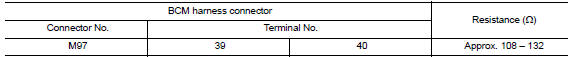
- Models without Intelligent Key system 
Is the measurement value within the specification?
YES >> GO TO 3.
NO >> Repair the BCM branch line.
3.CHECK POWER SUPPLY AND GROUND CIRCUIT
Check the power supply and the ground circuit of the BCM. Refer to the following.
- Models with Intelligent Key system: BCS "Diagnosis Procedure"
- Models without Intelligent Key system: BCS"Diagnosis Procedure"
Is the inspection result normal?
YES (Present error)>>Replace the BCM. Refer to the following.
- Models with Intelligent Key system: BCS "Removal and Installation"
- Models without Intelligent Key system: BCS "Removal and Installation"
YES (Past error)>>Error was detected in the BCM branch line.
NO >> Repair the power supply and the ground circuit.
 STRG Branch line circuit
Diagnosis Procedure 1.CHECK CONNECTOR 1. Turn the ignition switch OFF. 2. Disconnect the battery cable from the negative terminal. 3. Check the terminals and connectors of the steering angle senso ...
CAN Communication circuit
Diagnosis Procedure 1.CONNECTOR INSPECTION 1. Turn the ignition switch OFF. 2. Disconnect the battery cable from the negative terminal. 3. Disconnect all the unit connectors on CAN communication s ...
Other materials:
Ignition timing
Inspection
1.CHECK IGNITION TIMING
1. Attach timing light (A) to loop wire (1) as
shown.
2. Check ignition timing.
1 : Timing indicator
>> INSPECTION END
...
Exhaust system
Exploded View
1. Heated oxygen sensor 2 2. Catalyst cover (upper) 3. Seal bearing
4. Catalyst cover (lower) 5. Spring 6. Spring
7. Mounting rubber 8. Main muffler 9. Ring gasket
10. Center muffler 11. Mounting rubber 12. Seal bearing
13. Exhaust front tube
Removal and Installation
WARNIN ...
Categories
- Manuals Home
- Nissan Versa Owners Manual
- Nissan Versa Service Manual
- Video Guides
- Questions & Answers
- External Resources
- Latest Updates
- Most Popular
- Sitemap
- Search the site
- Privacy Policy
- Contact Us

0.006