Nissan Versa (N17): CAN Communication system
CAN Communication system : System Description
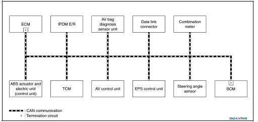
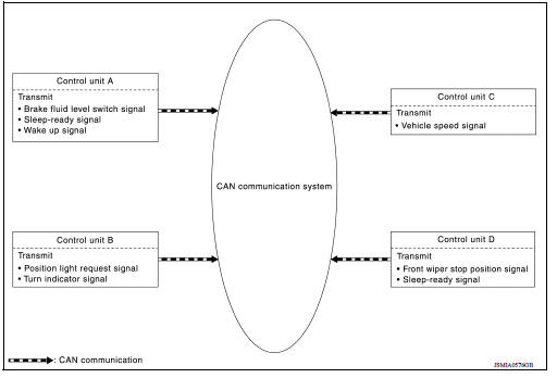
SYSTEM DIAGRAM
DESCRIPTION
CAN (Controller Area Network) is a serial communication line for real time application. It is an on-vehicle multiplex communication line with high data communication speed and excellent error detection ability. Many electronic control units are equipped onto a vehicle, and each control unit shares information and links with other control units during operation (not independent). In CAN communication, control units are connected with 2 communication lines (CAN-H line, CAN-L line) allowing a high rate of information transmission with less wiring.
Each control unit transmits/receives data but selectively reads required data only.
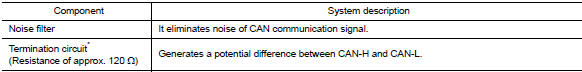
CAN COMMUNICATION SIGNAL GENERATION
- Termination circuits (resistors) are connected across the CAN communication system. When transmitting a CAN communication signal, each control unit passes a current to the CAN-H line and the current returns to the CAN-L line.
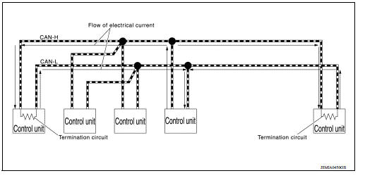
- The current flows separately into the termination circuits connected across the CAN communication system and the termination circuits drop voltage to generate a potential difference between the
CAN-H line and the CAN-L line.
NOTE: A signal with no current passage is called "Recessive" and one with current passage is called "Dominant".
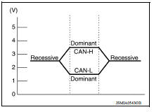
- The system produces digital signals for signal communications, by using the potential difference.
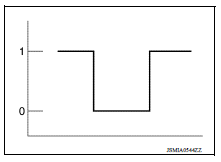
THE CONSTRUCTION OF CAN COMMUNICATION SIGNAL (MESSAGE)
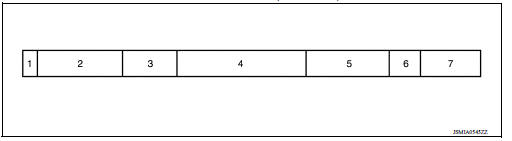
CAN Communication Line
The CAN communication line is a twisted pair wire consisting of strands of CAN-H (1) and CAN-L (2) and has noise immunity.
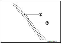
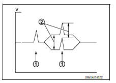
NOTE: The CAN communication system has the characteristics of noise-resistant because this system produces digital signals by using the potential difference between the CAN-H line and the CAN-L line and has the twisted pair wire structure.
Since the CAN-H line and the CAN-L line are always adjacent to each other, the same degree of noise occurs, respectively, when a noise (1) occurs. Although the noise changes the voltage, the potential difference (2) between the CAN-H line and the CAN-L line is insensitive to noise. Therefore, noise-resistant signals can be obtained.
CAN Signal Communications
Each control unit of the CAN communication system transmits signals through the CAN communication control circuit included in the control unit and receives only necessary signals from each control unit to perform various kinds of control.
- Example: Transmitted signals
- Example: Received signals
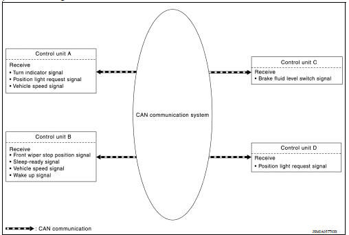
NOTE: The above signal names and signal communications are provided for reference purposes. For CAN communications signals of this vehicle, refer to LAN "CAN COMMUNICATION SYSTEM : CAN Communication Signal Chart".
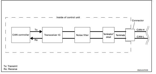
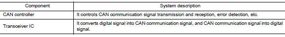
CAN COMMUNICATION SYSTEM : CAN Communication Control Circuit
CAN communication control circuit is incorporated into the control unit and transmits/receives CAN communication signals.
*: These are the only control units wired with both ends of CAN communication system.
CAN Communication system : CAN System Specification Chart
Determine CAN system type from the following specification chart.
NOTE: Refer to LAN, "Trouble Diagnosis Procedure" for how to use CAN system specification chart.
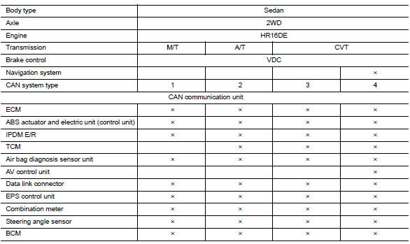
×: Applicable
VEHICLE EQUIPMENT IDENTIFICATION INFORMATION
NOTE: Check CAN system type from the vehicle shape and equipment.
1. NAVI switches A. With navigation system
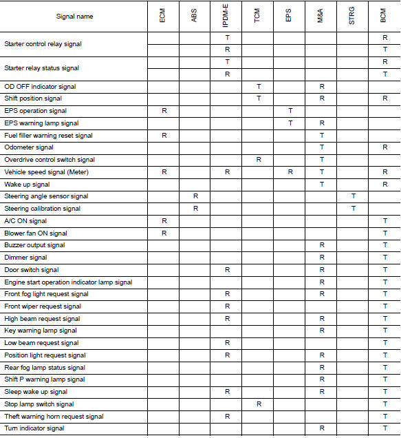
CAN COMMUNICATION SYSTEM : CAN Communication Signal Chart
Refer to LAN "How to Use CAN Communication Signal Chart" for how to use CAN communication signal chart.
NOTE:
- Refer to LAN "Abbreviation List" for the abbreviations of the connecting units.
- The AV control unit uses CAN communication only for communicating with the diagnostic tool (not with other connected control units).
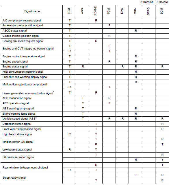
*: With battery current sensor (with battery temperature sensor)
NOTE: CAN data of the air bag diagnosis sensor unit is not used by usual service work, thus it is omitted.
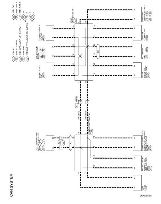
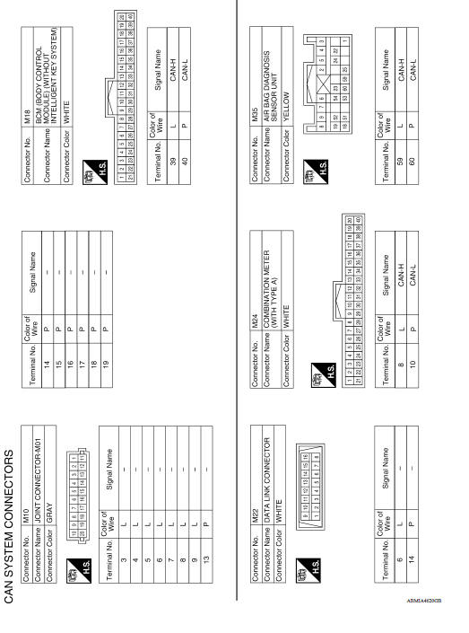
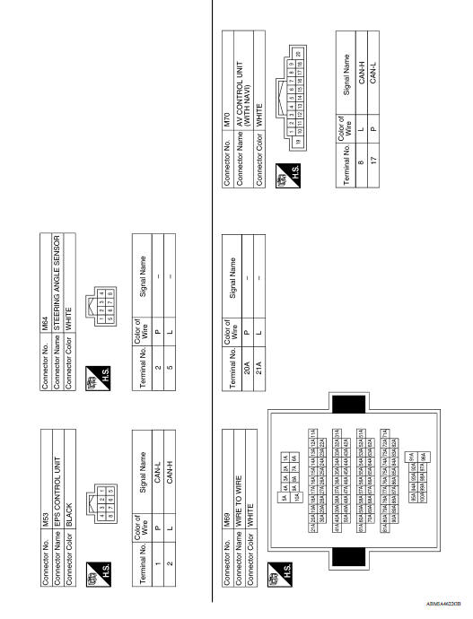
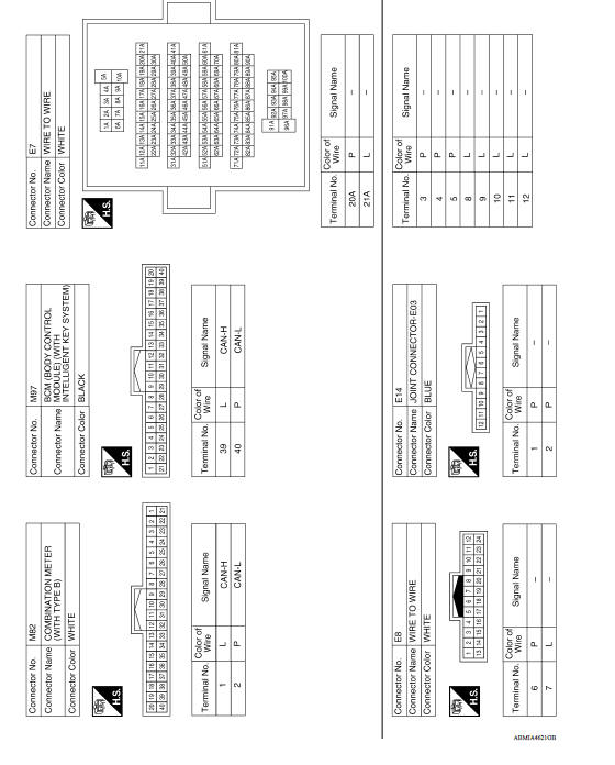
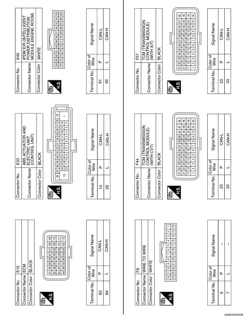
WIRING DIAGRAM
CAN SYSTEM
Wiring Diagram
BASIC INSPECTION
DIAGNOSIS AND REPAIR WORKFLOW
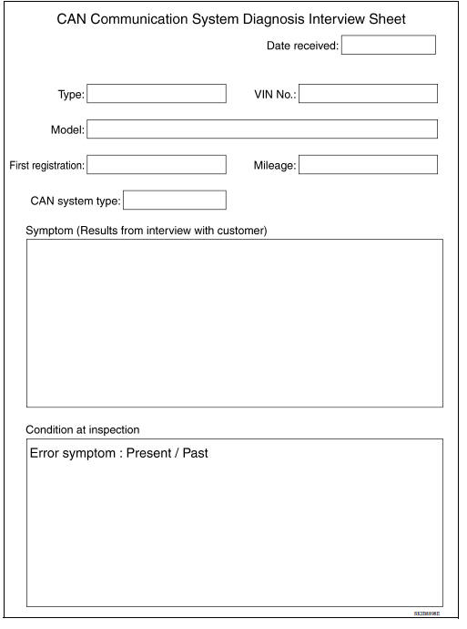
Interview Sheet
NOTE: Refer to LAN"Trouble Diagnosis Procedure" for how to use interview sheet.
DTC/CIRCUIT DIAGNOSIS
MALFUNCTION AREA CHART
Main Line
| Malfunction area | Reference |
| Main line between IPDM E/R and data link connector | LAN "Diagnosis Procedure" |
Branch Line
| Malfunction area | Reference |
| ECM branch line circuit | LAN "Diagnosis Procedure" |
| ABS actuator and electric unit (control unit) branch line circuit | LAN "Diagnosis Procedure" |
| IPDM E/R branch line circuit | LAN "Diagnosis Procedure" |
| TCM branch line circuit | LAN "Diagnosis Procedure" |
| Air bag diagnosis sensor unit branch line circuit | LAN "Diagnosis Procedure" |
| AV control unit branch line circuit | LAN "Diagnosis Procedure" |
| Data link connector branch line circuit | LAN"Diagnosis Procedure" |
| EPS control unit branch line circuit | LAN "Diagnosis Procedure" |
| Combination meter branch line circuit | LAN "Diagnosis Procedure" |
| Steering angle sensor branch line circuit | LAN "Diagnosis Procedure" |
| BCM branch line circuit | LAN "Diagnosis Procedure" |
Short Circuit
| Malfunction area | Reference |
| CAN communication circuit | LAN"Diagnosis Procedure" |
 Precautions
Main line between IPDM-E and DLC
circuit
Diagnosis Procedure 1.CHECK CONNECTOR 1. Turn the ignition switch OFF. 2. Disconnect the battery cable from the negative terminal. 3. Check the following terminals and connectors for damage, bend ...
Other materials:
Engine oil
Inspection
ENGINE OIL LEVEL
Park vehicle on a level surface, wait 10 minutes before checking the
engine oil level.
Pull out oil level gauge and wipe it clean.
Insert oil level gauge and make sure the engine oil level is within
the range (A) as shown.
If it is out of range, adjust it. ...
Calibration of G Sensor
Description
TCM stores calibration data (inherent characteristic value) of G sensor to
provide accurate control. Therefore,
it is required to perform calibration of G sensor after the following work is
performed.
Removal/installation or replacement of G sensor
Replacement of TCM
Work ...
Categories
- Manuals Home
- Nissan Versa Owners Manual
- Nissan Versa Service Manual
- Video Guides
- Questions & Answers
- External Resources
- Latest Updates
- Most Popular
- Sitemap
- Search the site
- Privacy Policy
- Contact Us

0.0072