Nissan Versa (N17): B2608 Starter relay
DTC Logic
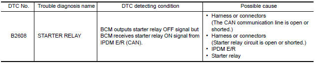
DTC DETECTION LOGIC
NOTE:
- If DTC B2608 is displayed with DTC U1000, first perform the trouble diagnosis for DTC U1000. Refer to BCS "DTC Logic".
- If DTC B2608 is displayed with DTC U1010, first perform the trouble diagnosis for DTC U1010. Refer to BCS "DTC Logic".
- If DTC B2608 is displayed with other DTC (BCM), first perform the
trouble diagnosis for other DTC detected.
DTC CONFIRMATION PROCEDURE
1.PERFORM DTC CONFIRMATION PROCEDURE
1. Press push-button ignition switch under the following conditions to start engine.
- Selector lever: In the P position
- Brake pedal: Depressed
2. Wait 1 second after engine started.
3. Check DTC in Self Diagnostic Result mode of BCM using CONSULT.
Is DTC detected?
YES >> Go to SEC "Diagnosis Procedure".
NO >> Inspection End.
Diagnosis Procedure
Regarding Wiring Diagram information, refer to SEC "Wiring Diagram".
1.CHECK DTC OF IPDM E/R
Check DTC in Self Diagnostic Result mode of IPDM E/R using CONSULT.
Is DTC detected?
YES >> Perform the trouble diagnosis related to the detected DTC. Refer to PCS "DTC Index".
NO >> GO TO 2.
2.CHECK STARTER RELAY POWER SUPPLY CIRCUIT
1. Turn ignition switch ON.
2. Check voltage between BCM harness connector and ground. 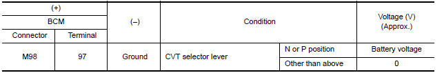
Is the inspection result normal?
YES >> GO TO 4.
NO >> GO TO 3.
3.CHECK STARTER RELAY CIRCUIT
1. Turn ignition switch OFF.
2. Disconnect starter relay.
3. Disconnect BCM connector.
4. Check continuity between starter relay harness connector and BCM harness
connector.
5. Check continuity between starter relay harness connector and ground.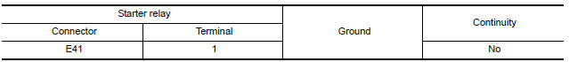
Is the inspection result normal?
YES >> GO TO 5.
NO >> Repair or replace harness.
4.CHECK STARTER RELAY
Refer to SEC "Component Inspection".
Is the inspection result normal?
YES >> GO TO 5.
NO >> Replace starter relay.
5.REPLACE BCM
1. Replace BCM. Refer to BCS "Removal and Installation".
2. Perform initialization of BCM and registration of all Intelligent Keys using CONSULT.
3. Perform DTC CONFIRMATION PROCEDURE for B2605. Refer to SEC "DTC Logic".
Is DTC B2605 detected again?
YES >> Replace IPDM E/R. Refer to PCS "Removal and Installation".
NO >> Inspection End.
Component Inspection
1.CHECK STARTER RELAY
1. Turn ignition switch OFF.
2. Disconnect starter relay.
3. Check continuity between starter relay terminals.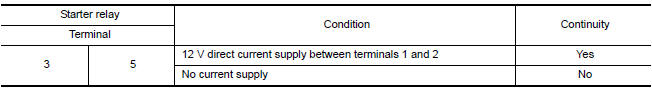
Is the inspection result normal?
YES >> Inspection End.
NO >> Replace starter relay.
 B2605 Shift position
B260F Engine status
Description BCM receives the engine status signal from ECM via CAN communication. ...
Other materials:
Power steering
WARNING
If the engine is not running or is turned
off while driving, the power assist for
the steering will not work. Steering will
be harder to operate.
When the power steering warning light
illuminates with the engine running,
there will be no power assist for the
steering. You w ...
OD OFF indicator lamp
Component Function Check
1.CHECK OD OFF INDICATOR LAMP FUNCTION
Check OD OFF indicator lamp turns ON for approx. 2 seconds when ignition
switch turns ON.
Is the inspection results normal?
YES >> INSPECTION END
NO >> Go to TM "Diagnosis Procedure".
Diagnosis Procedure
...
Categories
- Manuals Home
- Nissan Versa Owners Manual
- Nissan Versa Service Manual
- Video Guides
- Questions & Answers
- External Resources
- Latest Updates
- Most Popular
- Sitemap
- Search the site
- Privacy Policy
- Contact Us

0.0056