Nissan Versa (N17): P0335 CKP sensor (POC)
DTC Logic
DTC DETECTION LOGIC
| DTC No. | Trouble diagnosis name | DTC detecting condition | Possible cause |
| P0335 | Crankshaft position sensor (POS) circuit |
|
|
DTC CONFIRMATION PROCEDURE
1.PRECONDITIONING
If DTC Confirmation Procedure has been previously conducted, always perform the following procedure before conducting the next test.
- Turn ignition switch OFF and wait at least 10 seconds.
- Turn ignition switch ON.
- Turn ignition switch OFF and wait at least 10 seconds.
TESTING CONDITION: Before performing the following procedure, confirm that battery voltage is more than 10.5 V with ignition switch ON.
>> GO TO 2.
2.PERFORM DTC CONFIRMATION PROCEDURE
- Start engine and let it idle for at least 5 seconds.
If engine does not start, crank engine for at least 2 seconds.
- Check 1st trip DTC.
Is 1st trip DTC detected?
YES >> Go to EC, "Diagnosis Procedure".
NO >> INSPECTION END
Diagnosis Procedure
1.CHECK GROUND CONNECTION
- Turn ignition switch OFF.
- Check ground connection E15. Refer to Ground Inspection in GI, "Circuit Inspection".
Is the inspection result normal?
YES >> GO TO 2.
NO >> Repair or replace ground connection.
2.CHECK CRANKSHAFT POSITION (CKP) SENSOR (POS) POWER SUPPLY CIRCUITI
- Disconnect crankshaft position (CKP) sensor (POS) harness connector.
- Turn ignition switch ON.
- Check the voltage between CKP sensor (POS) harness connector and ground.
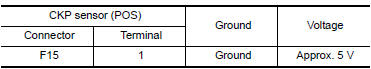
Is the inspection result normal?
YES >> GO TO 6.
NO >> GO TO 3.
3.CHECK CRANKSHAFT POSITION (CKP) SENSOR (POS) POWER SUPPLY CIRCUITII
- Turn ignition switch OFF.
- Disconnect ECM harness connector.
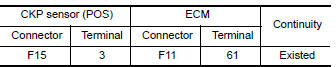
- Check the continuity between CKP sensor (POS) harness connector and ECM
harness connector
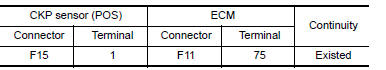 .
.
Is the inspection result normal?
YES >> GO TO 4.
NO >> Repair open circuit.
4.CHECK SENSOR POWER SUPPLY CIRCUIT
Check harness for short to power and short to ground, between
the following terminals. 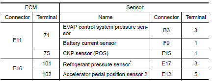
*: With A/C models
Is the inspection result normal?
YES >> GO TO 5.
NO >> Repair short to ground or short to power in harness or connectors.
5.CHECK COMPONENTS
Check the following.
- EVAP control system pressure sensor (Refer to EC, "Component Inspection").
- Battery current sensor (Refer to EC, "Component Inspection").
- Refrigerant pressure sensor (Refer to EC, "Component Function Check").
- Accelerator pedal position sensor (Refer to EC, "Component Inspection").
Is the inspection result normal?
YES >> GO TO 10.
NO >> Replace malfunctioning component.
6.CHECK CKP SENSOR (POS) GROUND CIRCUIT FOR OPEN AND SHORT
- Turn ignition switch OFF.
- Check the continuity between CKP sensor (POS) harness connector and ECM
harness connector.
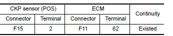
3. Also check harness for short to ground and short to power.
Is the inspection result normal?
YES >> GO TO 7.
NO >> Repair open circuit or short to ground or short to power in harness or connectors.
7.CHECK CKP SENSOR (POS) INPUT SIGNAL CIRCUIT FOR OPEN AND SHORT
- Disconnect ECM harness connector.
- Check the continuity between CKP sensor (POS) harness connector and ECM
harness connector.
3. Also check harness for short to ground and short to power.
Is the inspection result normal?
YES >> GO TO 8.
NO >> Repair open circuit or short to ground or short to power in harness or connectors.
8.CHECK CRANKSHAFT POSITION SENSOR (POS)
Refer to EC, "Component Inspection".
Is the inspection result normal?
YES >> GO TO 9.
NO >> Replace crankshaft position sensor (POS). Refer to EM, "Exploded View".
9.CHECK GEAR TOOTH
Visually check for chipping signal plate gear tooth.
Is the inspection result normal?
YES >> GO TO 10.
NO >> Replace the signal plate. Refer to EM, "Exploded View".
10.CHECK INTERMITTENT INCIDENT
Refer to GI, "Intermittent Incident".
>> INSPECTION END
Component Inspection
1.CHECK CRANKSHAFT POSITION SENSOR (POS)I
- Turn ignition switch OFF.
- Loosen the fixing bolt of the sensor.
- Disconnect crankshaft position sensor (POS) harness connector.
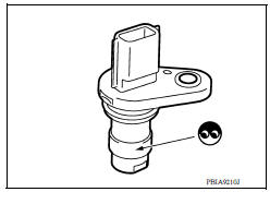
- Remove the sensor. Refer to EM94, "Exploded View".
- Visually check the sensor for chipping.
Is the inspection result normal?
YES >> GO TO 2.
NO >> Replace crankshaft position sensor (POS). Refer to EM, "Exploded View".
2.CHECK CRANKSHAFT POSITION SENSOR (POS)II
Check resistance between crankshaft position sensor (POS) terminals as
follows.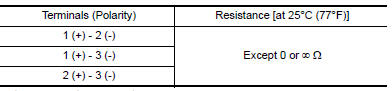
Is the inspection result normal?
YES >> INSPECTION END
NO >> Replace crankshaft position sensor (POS). Refer to EM, "Exploded View".
 P0327, P0328 KS
Other materials:
Uniform tire quality grading
DOT (Department of Transportation) Quality
Grades: All passenger car tires must conform to
federal safety requirements in addition to these
grades.
Quality grades can be found where applicable on
the tire sidewall between tread shoulder and
maximum section width. For example:
Treadwear 200 ...
Precaution
Precaution for Supplemental Restraint System
(SRS) "AIR BAG" and "SEAT BELT PRETENSIONER"
The Supplemental Restraint System such as "AIR BAG" and "SEAT BELT
PRETENSIONER", used along
with a front seat belt, helps to reduce the risk or severity of injury to the
driver and f ...
Categories
- Manuals Home
- Nissan Versa Owners Manual
- Nissan Versa Service Manual
- Video Guides
- Questions & Answers
- External Resources
- Latest Updates
- Most Popular
- Sitemap
- Search the site
- Privacy Policy
- Contact Us

0.0055