Nissan Versa (N17): Inside key antenna
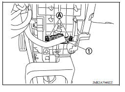
Instrument center
INSTRUMENT CENTER : Removal and Installation
REMOVAL
1. Remove the instrument lower center panel. Refer to IP "Removal and Installation".
2. Remove screws (A) and the inside key antenna (instrument center) (1).
INSTALLATION
Installation is in the reverse order of removal.
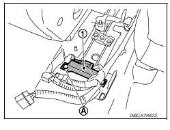
Console
CONSOLE : Removal and Installation
REMOVAL
1. Remove the center console assembly. Refer to IP "Removal and Installation".
2. Remove clips (A) and the inside key antenna (console) (1).
INSTALLATION
Installation is in the reverse order of removal.
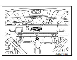
Trunk room
TRUNK ROOM : Removal and Installation
REMOVAL
Remove clips (A) and the inside key antenna (trunk room) (1).
INSTALLATION
Installation is in the reverse order of removal.
 Door switch
Exploded View 1. Door switch 2. Door switch bolt Removal and Installation REMOVAL 1. Remove the door switch bolt (A). 2. Disconnect the harness connector and remove door switch (1). INST ...

Other materials:
Camshaft
Exploded View
1. Camshaft bracket (No. 2 to 5) 2. Camshaft bracket (No. 1) 3. Camshaft
sprocket (EXH)
4. Exhaust valve timing control solenoid
valve 5. Oring 6. Camshaft sprocket (INT)
7. Plug (EXH) 8. Washer (EXH) 9. Oil filter (for exhaust valve timing control
solenoid valve)
10. Cylinde ...
P0979 Shift solenoid C
DTC Logic
DTC DETECTION LOGIC
DTC
Trouble diagnosis name
DTC detection condition
Possible causes
P0979
Shift Solenoid C Control Circuit
Low
The following diagnosis conditions
are met, and the current
monitor reading of the TCM 2-4
brake solenoid valve is ...
Categories
- Manuals Home
- Nissan Versa Owners Manual
- Nissan Versa Service Manual
- Video Guides
- Questions & Answers
- External Resources
- Latest Updates
- Most Popular
- Sitemap
- Search the site
- Privacy Policy
- Contact Us

0.0062