
Nissan Versa (N17): Diagnosis system (combination meter)
Diagnosis Description
ON BOARD DIAGNOSIS ITEM
The information display, speedometer and tachometer can be checked in self-diagnosis mode.
NOTE:
- Check combination meter power supply and ground circuits if self-diagnosis mode does not start. Refer to MWI "COMBINATION METER : Diagnosis Procedure". Replace combination meter if power supply and ground circuits are found to be normal and self-diagnosis mode does not start. Refer to MWI "Removal and Installation".
- Combination meter self-diagnosis mode will function with the ignition switch in ON. Combination meter selfdiagnosis mode will exit upon turning the ignition switch to OFF.
METHOD OF STARTING
1. Turn the ignition switch OFF.
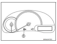
2. Turn the ignition switch ON while pressing and holding the switch (1) for 0.8 seconds or more.
3. Press the  switch at least 3
times. (Within 7 seconds after the ignition switch is turned ON.)
switch at least 3
times. (Within 7 seconds after the ignition switch is turned ON.)
4. The combination meter is turned to self-diagnosis mode.
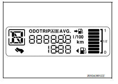
- All segments of the information display are displayed.
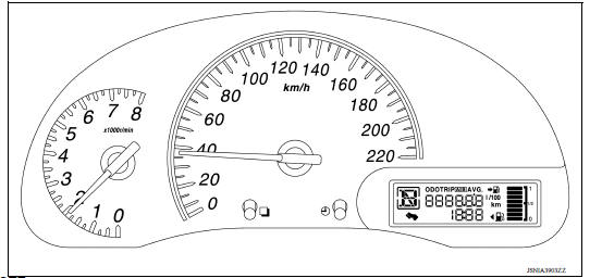
5. Each meter activates by pressing the switch.
NOTE:
- If any of the meters or gauges is not activated, replace combination meter.
- The figure is reference.
Consult Function
APPLICATION ITEMS
CONSULT can display each diagnostic item using the diagnostic test modes
shown. 
SELF DIAG RESULT
Refer to MWI "DTC Index".
DATA MONITOR
Display Item List
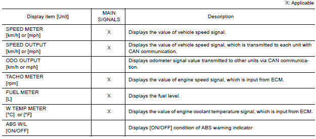
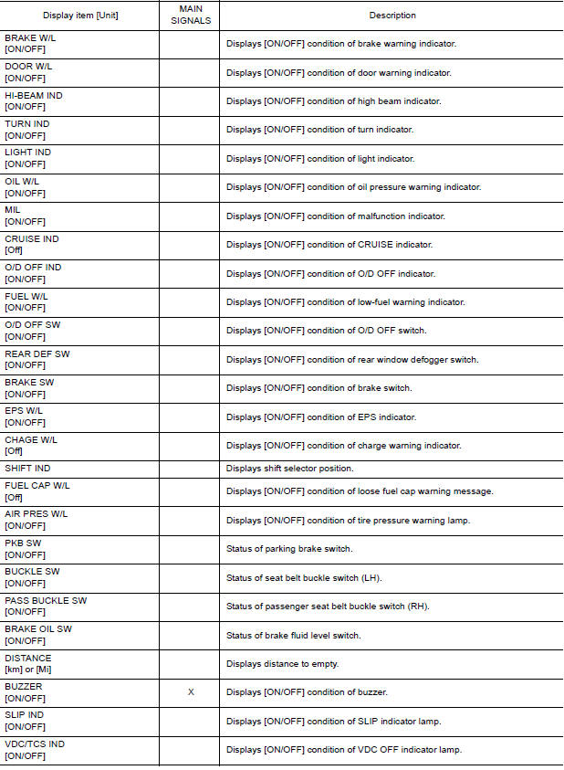
NOTE: Some items are not available according to vehicle specification.
SPECIAL FUNCTION
Special menu 
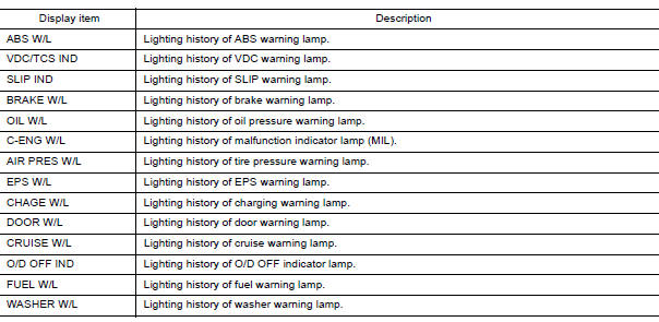
W/L ON HISTORY
- Stores histories when warning/indicator lamp is turned on.
- "W/L ON HISTORY" indicates the "TIME" when the warning/ indicator lamp is turned on.
- The "TIME" above is:
- 0: The condition that the warning/indicator lamp has been turned on 1 or more times after starting the engine and waiting for 30 seconds.
- 1 - 39: The number of times the engine was restarted after the 0 condition.
- NO W/L ON HISTORY: Stores NO (0) turning on history of warning/indicator lamp.
NOTE:
- W/L ON HISTORY is not stored for approximately 30 seconds after the engine starts.
- Brake warning lamp does not store any history when the parking brake is applied or the brake fluid level gets low.
Display Item
ECU DIAGNOSIS INFORMATION
COMBINATION METER
Reference Value
VALUES ON THE DIAGNOSIS TOOL
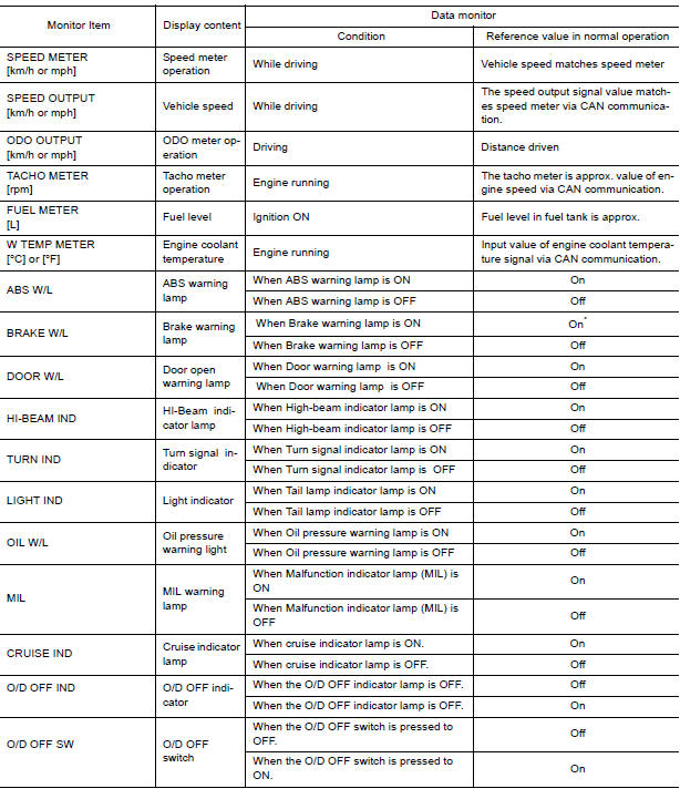
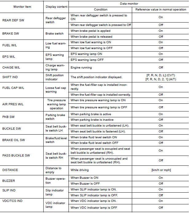
*: Displays "OFF" if the brake warning lamp is illuminated when the valve check starts, the parking brake switch is turned ON or the brake fluid level switch is turned ON.
NOTE: Some items are not available according to vehicle specification.
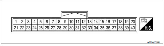
TERMINAL LAYOUT
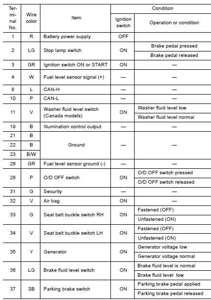
PHYSICAL VALUES
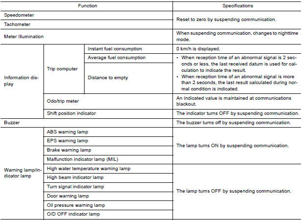
Fail-Safe
The combination meter activates the fail-safe control if CAN communication with each unit is malfunctioning.
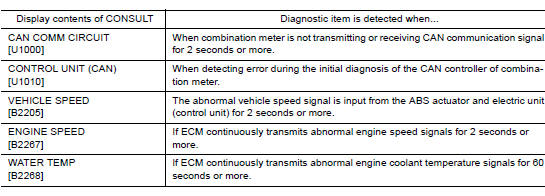
DTC Index
BCM (BODY CONTROL MODULE)
List of ECU Reference
| ECU | Reference |
| BCM | BCS "Reference Value" |
| BCS "Wiring Diagram" | |
| BCS "Fail-safe" | |
| BCS "DTC Inspection Priority Chart" | |
| BCS "DTC Index" |
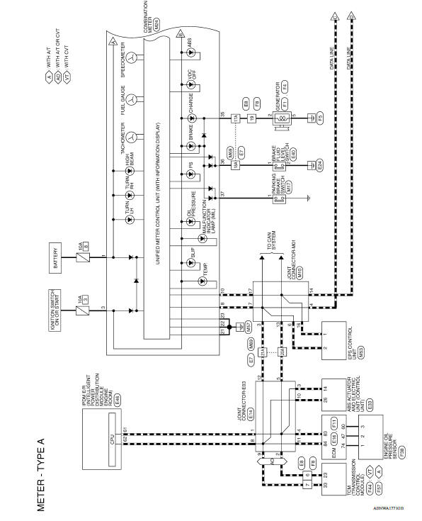
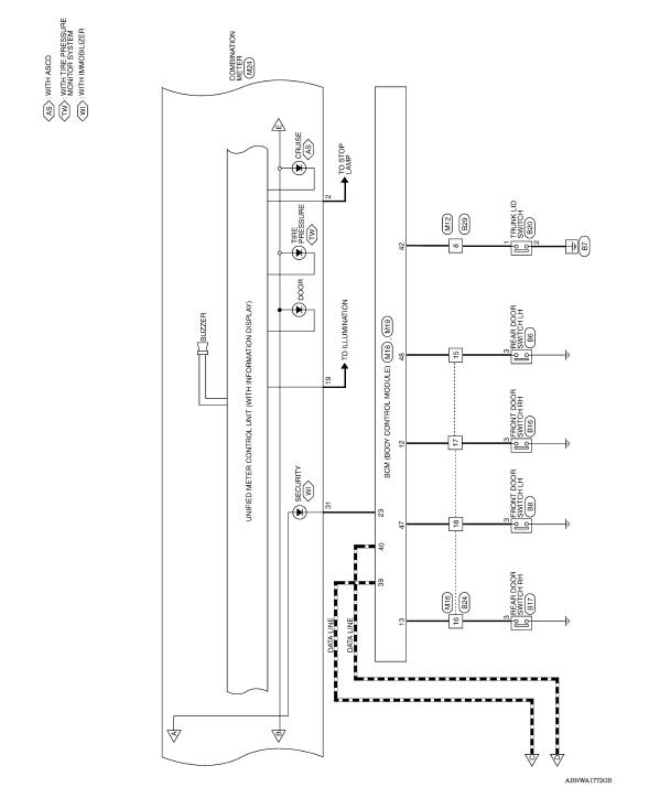
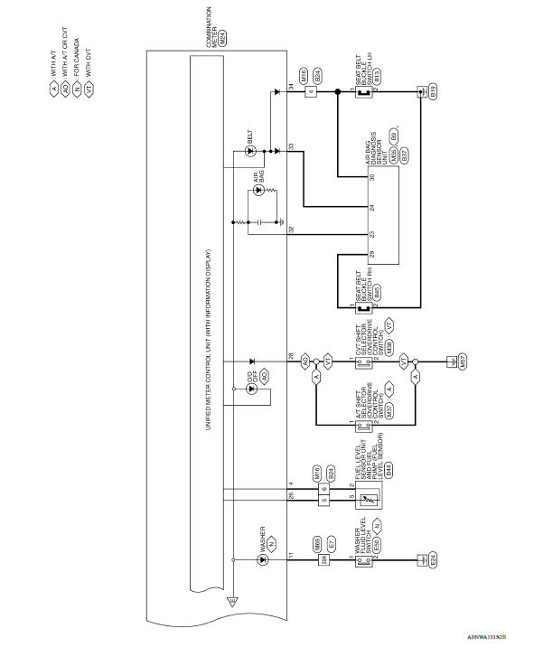
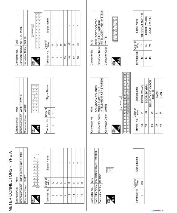
WIRING DIAGRAM
METER SYSTEM
Wiring Diagram
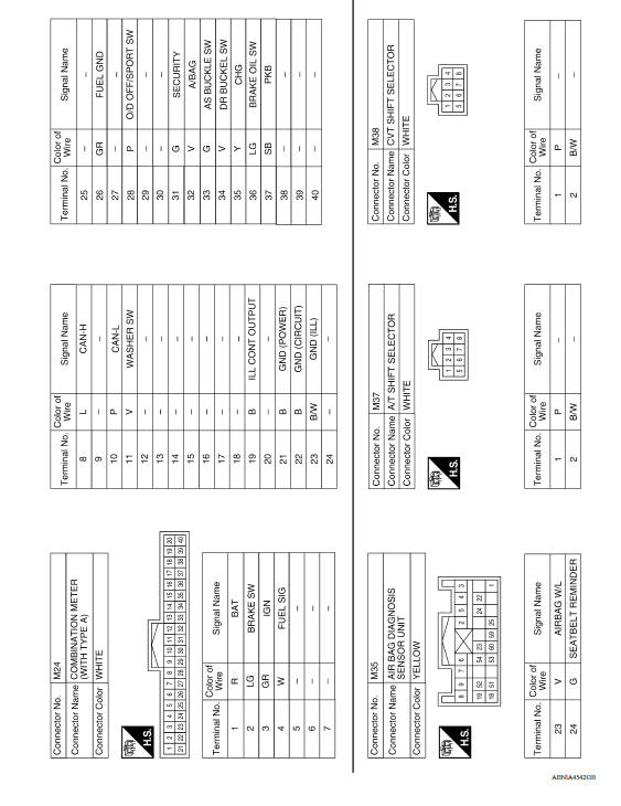
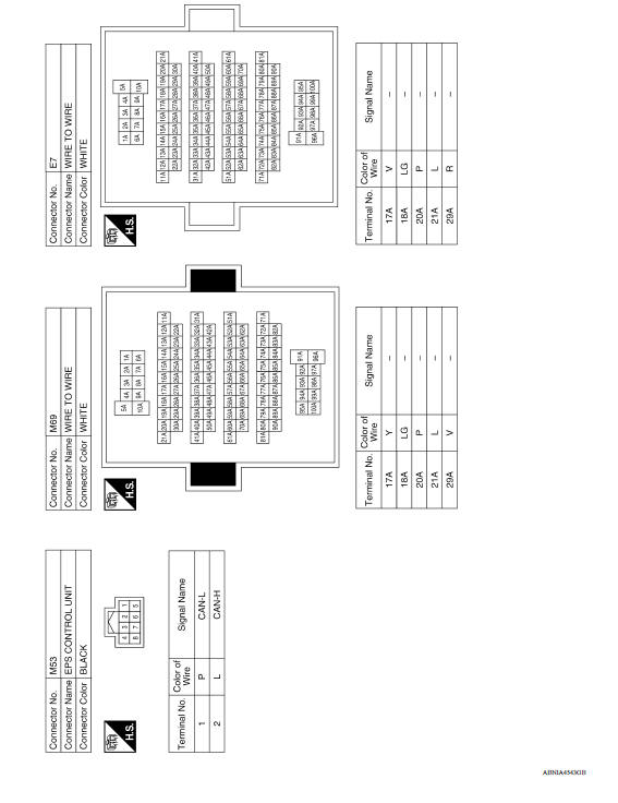
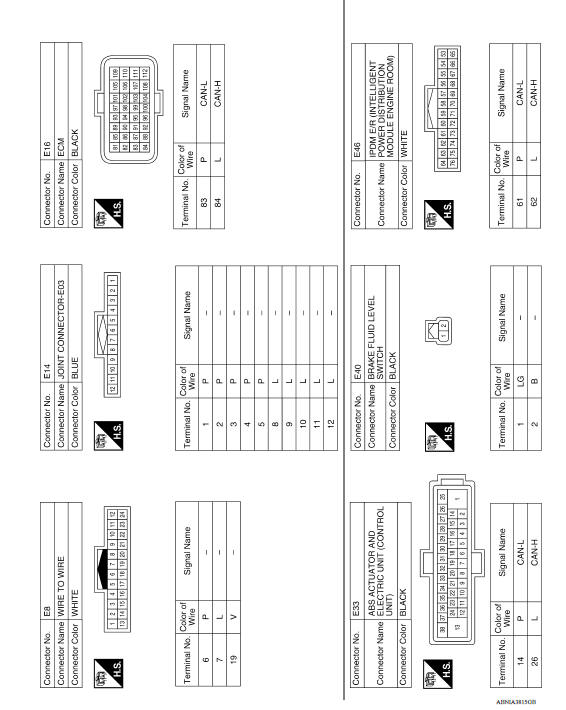
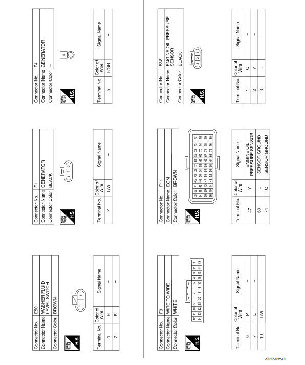
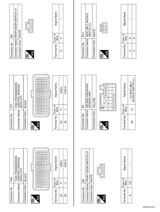
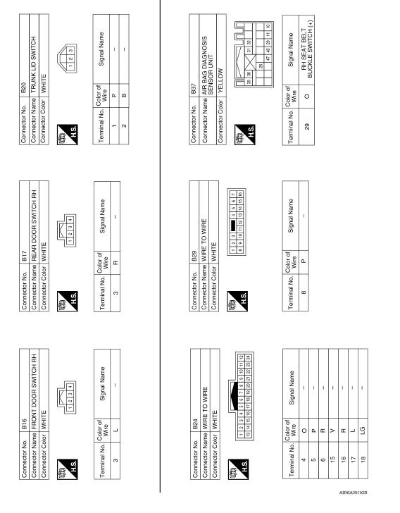
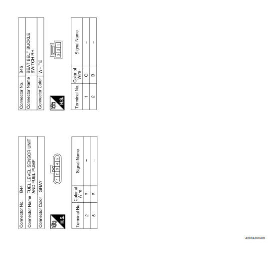
BASIC INSPECTION
 System
Diagnosis and repair workflow
Work Flow OVERALL SEQUENCE DETAILED FLOW 1.CONFIRM SYMPTOM Confirm symptom or customer complaint. >> GO TO 2 2.SELF-DIAGNOSIS OF COMBINATION METER Perform self-diagnosis of combinat ...
Other materials:
Unexpected pedal reaction
Diagnosis Procedure
1.CHECK BRAKE PEDAL STROKE
Check brake pedal stroke. Refer to BR "Inspection and Adjustment".
Is the stroke too big?
YES >>
Bleed air from brake line and hose. Refer to BR "Bleeding Brake System".
Check brake pedal, brake booster, and master cy ...
Diagnosis and repair workflow
Workflow
OVERALL SEQUENCE
DETAILED FLOW
1.INTERVIEW CUSTOMER
Interview the customer to obtain as much information as possible about the
conditions and environment under
which the malfunction occurred.
>> GO TO 2.
2.SYMPTOM CHECK
Verify symptoms.
>> GO TO 3.
3.CHECK FOR DT ...
Categories
- Manuals Home
- Nissan Versa Owners Manual
- Nissan Versa Service Manual
- Video Guides
- Questions & Answers
- External Resources
- Latest Updates
- Most Popular
- Sitemap
- Search the site
- Privacy Policy
- Contact Us

0.0068