Nissan Versa (N17): P1586 G Sensor
DTC Logic
DTC DETECTION LOGIC
| DTC | Trouble diagnosis name | DTC detection condition | Possible causes |
| P1586 | G Sensor Circuit Electrical | When the following diagnosis conditions are
satisfied and the detection conditions are satisfied
twice in the same DC: - Diagnosis conditions - While driving - TCM power supply voltage: More than 11 V - Detection condition - The G sensor detection voltage is 0.7 V or less continuously for 5 seconds or more. |
- Harness or connector
(G sensor circuit) - G sensor |
| When the following diagnosis conditions are
satisfied and the detection conditions are satisfied
twice in the same DC: - Diagnosis conditions - While driving - TCM power supply voltage: More than 11 V - Detection condition - The G sensor detection voltage is 3.2 V or more continuously for 5 seconds or more |
NOTE: DC stands for "DRIVING CYCLE" and indicates a series of driving cycle of "Ignition switch OFF → ON → driving → OFF".
DTC CONFIRMATION PROCEDURE
CAUTION: Be careful of the driving speed.
1.PREPARATION BEFORE WORK
If another "DTC CONFIRMATION PROCEDURE" occurs just before, turn ignition switch OFF and wait for at least 10 seconds, then perform the next test.
>> GO TO 2.
2.CHECK DTC DETECTION
With CONSULT
- Start the engine.
- Drive the vehicle for 10 seconds or more.
- Stop the vehicle.
CAUTION: Never stop the engine.
- Repeat step 2 through 3.
- Check the DTC.
Is "P1586" detected?
YES >> Go to TM "Diagnosis Procedure".
NO >> INSPECTION END
Diagnosis Procedure
1.CHECK G SENSOR SIGNAL
With CONSULT
- Park the vehicle on a level surface.
- Turn ignition switch ON.
- Select "Data Monitor" in "TRANSMISSION".
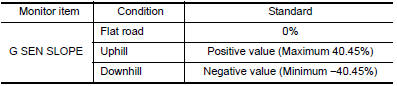
- Select "G SEN SLOPE".
- Swing the vehicle and check if value varies between −40.45% and 40.45%.
Is the inspection result normal?
YES >> GO TO 2.
NO >> GO TO 3.
2.G SENSOR CALIBRATION (PART 1)
With CONSULT
- Select "Self Diagnostic Results" in "TRANSMISSION".
- Touch "Erase".
>> Perform "G SENSOR CALIBRATION". Refer to TM "Work Procedure".
3.CHECK SENSOR POWER SUPPLY
- Turn ignition switch OFF.
- Disconnect G sensor connector.
- Turn ignition switch ON.
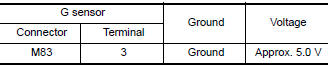
- Check voltage between G sensor harness connector terminal and ground.
Is the inspection result normal?
YES >> GO TO 4.
NO >> GO TO 8.
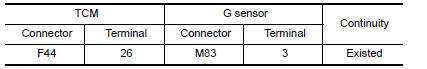
4.CHECK CIRCUIT BETWEEN TCM AND G SENSOR (PART 1)
- Turn ignition switch OFF.
- Disconnect TCM connector.
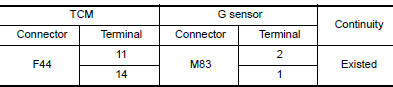
- Check continuity between TCM harness connector terminals and G sensor
harness connector terminals.
Is the inspection result normal?
YES >> GO TO 5.
NO >> Repair or replace malfunctioning parts.
5.CHECK CIRCUIT BETWEEN TCM AND G SENSOR (PART 2)
Check continuity between TCM harness connector terminals and ground. 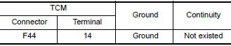
Is the inspection result normal?
YES >> GO TO 6.
NO >> Repair or replace malfunctioning parts.
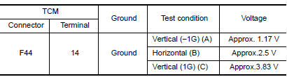
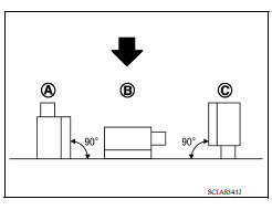
6.CHECK G SENSOR
- Remove G sensor. TM "Removal and Installation".
- Connect the all connectors.
- Turn ignition switch ON.
- Check voltage between TCM harness connector terminal and ground.
 : Direction of gravitational
force
: Direction of gravitational
force
Is the inspection result normal?
YES >> GO TO 7.
NO >> Replace G sensor.TM "Removal and Installation".
7.G SENSOR CALIBRATION (PART 2)
With CONSULT
- Install G sensor. TM "Removal and Installation".
- Select "Self Diagnostic Results" in "TRANSMISSION".
- Touch "Erase".
>> Perform "G SENSOR CALIBRATION". Refer to TM "Work Procedure".
8.CHECK SENSOR POWER SUPPLY CIRCUIT (PART 1)
- Turn ignition switch OFF.
- Disconnect TCM connector.
- Check continuity between TCM harness connector terminal and G sensor
harness connector terminal.
Is the inspection result normal?
YES >> GO TO 9.
NO >> Repair or replace malfunctioning parts.
9.CHECK SENSOR POWER SUPPLY CIRCUIT (PART 2)
Check continuity between TCM harness connector terminal and ground. 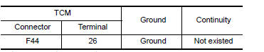
Is the inspection result normal?
YES >> Check intermittent incident. Refer to GI "Intermittent Incident".
NO >> Repair or replace malfunctioning parts.
 P099C Shift solenoid G
Other materials:
Diagnosis and repair work flow
Work Flow
OVERALL SEQUENCE
DETAILED FLOW
1.COLLECT INFORMATION FROM THE CUSTOMER
Get detailed information from the customer about the symptom (the condition
and the environment when the
incident/malfunction occurred) using the diagnostic worksheet. Refer to BRC
"Diagnostic Work Sh ...
Steering wheel turning force is heavy or light
Description
Steering wheel turning force is heavy or light.
Diagnosis Procedure
1.PERFORM SELF-DIAGNOSIS
With CONSULT
Turn the ignition switch OFF to ON.
Perform "EPS" self-diagnosis.
Is any DTC detected?
YES >> Check the DTC. Refer to STC "DTC Index".
NO >> GO ...
Categories
- Manuals Home
- Nissan Versa Owners Manual
- Nissan Versa Service Manual
- Video Guides
- Questions & Answers
- External Resources
- Latest Updates
- Most Popular
- Sitemap
- Search the site
- Privacy Policy
- Contact Us

0.0073