Nissan Versa (N17): Front wiper motor hi circuit
Component Function Check
1.CHECK FRONT WIPER HI OPERATION
IPDM E/R AUTO ACTIVE TEST
1. Start IPDM E/R auto active test. Refer to PCS "Diagnosis Description" or PCS "Diagnosis Description".
2. Check that the front wiper operates on HI operation.
CONSULT ACTIVE TEST
1. Select FR WIPER of BCM (WIPER) active test item.
2. Check front wiper operation.
HI : Front wiper (HI) operation
OFF : Front wiper OFF
Is the inspection result normal?
YES >> Front wiper motor HI circuit is normal.
NO >> Refer to WW "Diagnosis Procedure".
Diagnosis Procedure
Regarding Wiring Diagram information, refer to WW "Wiring Diagram".
1. CHECK FRONT WIPER MOTOR FUSE
1. Turn the ignition switch OFF.
2. Check that the following fuse is not blown.
Is the fuse blown?
YES >> Replace the fuse after repairing the affected circuit.
NO >> GO TO 2
2. CHECK FRONT WIPER MOTOR (HI) OUTPUT VOLTAGE
1. Turn the ignition switch ON.
2. Select FR WIPER of BCM (WIPER) active test item.
3. While performing the active test, check voltage between IPDM E/R harness
connector and ground.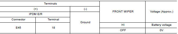
Is the inspection result normal?
YES >> GO TO 3
NO >> Replace IPDM E/R. Refer to PCS "Removal and Installation".
3. CHECK FRONT WIPER MOTOR (HI) OPEN CIRCUIT
1. Turn the ignition switch OFF.
2. Disconnect IPDM E/R and front wiper motor.
3. Check continuity between IPDM E/R harness connector and front wiper motor
harness connector.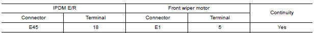
Is the inspection result normal?
YES >> Replace front wiper motor. Refer to WW "WIPER DRIVE ASSEMBLY : Removal and Installation".
NO >> Repair or replace harness.
 Front wiper motor lo circuit
Other materials:
Wiper and washer switch
Switch operation
Type A (if so equipped)
The windshield wiper and washer operates when
the ignition switch is in the ON position.
Push the lever down to operate the wiper at the
following speed:
Intermittent (INT) - intermittent operation
can be adjusted by turning the knob toward
...
P072D Stuck in 2GR
DTC Logic
DTC DETECTION LOGIC
DTC
Trouble diagnosis name
DTC detection condition
Possible causes
P072D
Stuck in Gear 2
The following diagnosis conditions
are met and the detection
conditions continue for 0.5 seconds
or more.- Diagnosis condition
- Shiftin ...
Categories
- Manuals Home
- Nissan Versa Owners Manual
- Nissan Versa Service Manual
- Video Guides
- Questions & Answers
- External Resources
- Latest Updates
- Most Popular
- Sitemap
- Search the site
- Privacy Policy
- Contact Us

0.0055