Nissan Versa (N17): Front wiper motor lo circuit
Component Function Check
1.CHECK FRONT WIPER LO OPERATION
IPDM E/R AUTO ACTIVE TEST
1. Start IPDM E/R auto active test. Refer to PCS "Diagnosis Description" or PCS "Diagnosis Description".
2. Check that the front wiper operates on LO operation.
CONSULT ACTIVE TEST
1. Select FR WIPER of BCM (WIPER) active test item.
2. Check front wiper operation.
LO : Front wiper (LO) operation
OFF : Front wiper OFF
Is the inspection result normal?
YES >> Front wiper motor LO circuit is normal.
NO >> Refer to WW "Diagnosis Procedure".
Diagnosis Procedure
Regarding Wiring Diagram information, refer to WW "Wiring Diagram".
1. CHECK FRONT WIPER MOTOR FUSE
1. Turn the ignition switch OFF.
2. Check that the following fuse is not blown.
Is the fuse blown?
YES >> Replace the fuse after repairing the affected circuit.
NO >> GO TO 2
2. CHECK FRONT WIPER MOTOR (LO) OUTPUT VOLTAGE
1. Turn the ignition switch ON.
2. Select FR WIPER of BCM (WIPER) active test item.
3. While performing the active test, check voltage between IPDM E/R harness
connector and ground.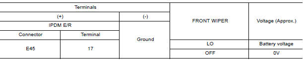
Is the inspection result normal?
YES >> GO TO 3
NO >> Replace IPDM E/R. Refer to PCS "Removal and Installation".
3. CHECK FRONT WIPER MOTOR (LO) OPEN CIRCUIT
1. Turn the ignition switch OFF.
2. Disconnect IPDM E/R and front wiper motor.
3. Check continuity between IPDM E/R harness connector and front wiper motor
harness connector.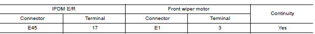
Is the inspection result normal?
YES >> Replace front wiper motor. Refer to WW "WIPER DRIVE ASSEMBLY : Removal and Installation".
NO >> Repair or replace harness.
 Wiper and washer fuse
Description Diagnosis Procedure 1. CHECK FUSES Check that the following fuses are not blown. Is the f ...

Other materials:
Starting the engine (models with NISSAN Intelligent Key system)
1. Apply the parking brake.
2. Move the shift lever to P (Park) or N (Neutral).
P (Park) is recommended.
The starter is designed not to operate if
the shift lever is in any of the driving
positions.
3. Push the ignition switch to the ON position.
Depress the brake pedal and push the ...
Power steering fluid
Check the fluid level in the reservoir.
The fluid level should be checked when the fluid
is cold at fluid temperatures of 32 to 86ºF (0 to
30ºC). The fluid level can be checked with the
level gauge which is attached to the cap. To
check the fluid level, remove the cap. The fluid ...
Categories
- Manuals Home
- Nissan Versa Owners Manual
- Nissan Versa Service Manual
- Video Guides
- Questions & Answers
- External Resources
- Latest Updates
- Most Popular
- Sitemap
- Search the site
- Privacy Policy
- Contact Us

0.0062