Nissan Versa (N17): Overdrive control switch
Component Function Check
1.CHECK O/D INDICATOR LAMP FUNCTION
Check O/D OFF indicator lamp turns ON for approx. 2 seconds when ignition switch turns ON.
Is the inspection results normal?
YES >> GO TO 2.
NO >> Go to TM, "Diagnosis Procedure".
2.CHECK O/D SWITCH FUNCTION
- Shift the selector lever to "D" position.
- Check that O/D OFF indicator lamp turns ON/OFF when sport mode switch is operated.
Is the inspection results normal?
YES >> INSPECTION END
NO >> Go to TM, "Diagnosis Procedure".
Diagnosis Procedure
1.CHECK OVERDRIVE CONTROL SWITCH CIRCUIT
- Turn ignition switch OFF.
- Disconnect A/T shift selector connector.
- Turn ignition switch ON.
- Check the voltage between A/T shift selector harness connector
terminals.
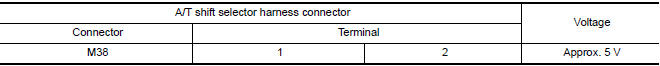
Is the inspection result normal?
YES >> GO TO 2.
NO >> GO TO 3.
2.CHECK OVERDRIVE CONTROL SWITCH
Check overdrive control switch. Refer to TM, "Component Inspection (Overdrive Control Switch)".
Is the inspection result normal?
YES >> Check intermittent incident. Refer to GI "Intermittent Incident".
NO >> Repair or replace the malfunctioning parts.
3.CHECK GROUND CIRCUIT
Check the continuity between A/T shift selector harness connector terminal
and ground. 
Is the inspection result normal?
YES >> GO TO 4.
NO >> Repair or replace the malfunctioning parts.
4.CHECK CIRCUIT BETWEEN COMBINATION METER AND A/T SHIFT SELECTOR (PART 1)
- Turn ignition switch OFF.
- Disconnect combination meter connector.
- Check the continuity between combination meter harness connector
terminal and A/T shift selector harness
connector terminal.
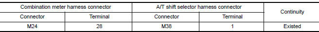
Is the inspection result normal?
YES >> GO TO 5.
NO >> Repair or replace the malfunctioning parts.
5.CHECK CIRCUIT BETWEEN COMBINATION METER AND A/T SHIFT SELECTOR (PART 2)
Check the continuity between combination meter harness connector terminal and
ground. 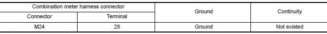
Is the inspection result normal?
YES >> GO TO 6.
NO >> Repair or replace the malfunctioning parts.
6.CHECK COMBINATION METER INPUT SIGNAL
- Connect all of the disconnected connectors.
- Turn ignition switch ON.
- Select "Data Monitor" in "METER/M&A".
- Select "O/D OFF SW".
- Check that "O/D OFF SW" turns ON/OFF when overdrive control switch is operated. Refer to MWI, "Reference Value".
Is the inspection result normal?
YES >> Check intermittent incident. Refer to GI "Intermittent Incident".
NO >> Replace combination meter. Refer to MWI "Removal and Installation".
Component Inspection (Overdrive Control Switch)
1.CHECK OVERDRIVE CONTROL SWITCH
Check the continuity between wires of selector lever knob (1) 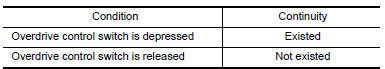
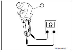
Is the inspection result normal?
YES >> INSPECTION END
NO >> Replace the selector lever knob. Refer to TM "Removal and Installation".
 Main power supply and ground circuit
Diagnosis Procedure 1.CHECK TCM POWER CIRCUIT 1 Turn the ignition switch OFF. Disconnect the TCM connector. Check the voltage between the TCM harness connector terminals and ground. ...
O/D OFF indicator lamp
Component Function Check 1.CHECK O/D OFF INDICATOR LAMP FUNCTION Check O/D OFF indicator lamp turns ON for approx. 2 seconds when ignition switch turns ON. Is the inspection results normal? YE ...
Other materials:
P0974 Shift solenoid A
DTC Logic
DTC DETECTION LOGIC
DTC
Trouble diagnosis name
DTC detection condition
Possible causes
P0974
Shift Solenoid "A" Control Circuit
High
The following diagnosis conditions
are met, and the TCM select
switch ON-OFF solenoid
valve monitor value is OF ...
Wheel alignment
Inspection
DESCRIPTION
CAUTION:
The adjustment mechanisms of camber and toe-in are not included.
If camber and toe-in is outside the standard, check front
suspension parts for wear and damage.
Replace suspect parts if a malfunction is detected.
Measure wheel alignment under unladen ...
Categories
- Manuals Home
- Nissan Versa Owners Manual
- Nissan Versa Service Manual
- Video Guides
- Questions & Answers
- External Resources
- Latest Updates
- Most Popular
- Sitemap
- Search the site
- Privacy Policy
- Contact Us

0.0074