Nissan Versa (N17): DLC Branch line circuit
Diagnosis Procedure
1.CHECK CONNECTOR
1. Turn the ignition switch OFF.
2. Disconnect the battery cable from the negative terminal.
3. Check the terminals and connectors of the data link connector for damage, bend and loose connection (connector side and harness side).
Is the inspection result normal?
YES >> GO TO 2.
NO >> Repair the terminal and connector.
2.CHECK HARNESS FOR OPEN CIRCUIT
Check the resistance between the data link connector terminals.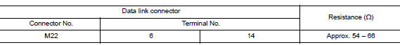
Is the measurement value within the specification?
YES (Present error)>>Check CAN system type decision again.
YES (Past error)>>Error was detected in the data link connector branch line circuit.
NO >> Repair the data link connector branch line.
 AV Branch line circuit
Diagnosis Procedure 1.CHECK CONNECTOR 1. Turn the ignition switch OFF. 2. Disconnect the battery cable from the negative terminal. 3. Check the terminals and connectors of the AV control unit for ...
EPS Branch line circuit
Diagnosis Procedure 1.CHECK CONNECTOR 1. Turn the ignition switch OFF. 2. Disconnect the battery cable from the negative terminal. 3. Check the terminals and connectors of the EPS control unit f ...
Other materials:
Final drive
Exploded View
1. Differential side bearing outer race 2. Differential side bearing 3. Final
drive
: Replace the parts as a set.
Disassembly
Remove differential side bearings, using Tool (A) and suitable tool.
Tool number : ST33052000 ( - )
Assembly
Install differential sid ...
Front
FRONT : Exploded View
1. Master cylinder brake pipe assembly
(front)
2. Master cylinder brake pipe assembly
(rear)
3. ABS actuator to connector brake
pipe assembly (RH)
4. ABS actuator to connector brake
pipe assembly (LH)
5. Brake pipe connector 6. Brake pipe assembly (RH front)
7. B ...
Categories
- Manuals Home
- Nissan Versa Owners Manual
- Nissan Versa Service Manual
- Video Guides
- Questions & Answers
- External Resources
- Latest Updates
- Most Popular
- Sitemap
- Search the site
- Privacy Policy
- Contact Us

0.0048