Nissan Versa (N17): AV Branch line circuit
Diagnosis Procedure
1.CHECK CONNECTOR
1. Turn the ignition switch OFF.
2. Disconnect the battery cable from the negative terminal.
3. Check the terminals and connectors of the AV control unit for damage, bend and loose connection (unit side and connector side).
Is the inspection result normal?
YES >> GO TO 2.
NO >> Repair the terminal and connector.
2.CHECK HARNESS FOR OPEN CIRCUIT
1. Disconnect the connector of AV control unit.
2. Check the resistance between the AV control unit harness connector
terminals.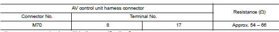
Is the measurement value within the specification?
YES >> GO TO 3.
NO >> Repair the AV control unit branch line.
3.CHECK POWER SUPPLY AND GROUND CIRCUIT
Check the power supply and the ground circuit of the AV control unit. Refer to AV "AV CONTROL UNIT : Diagnosis Procedure".
Is the inspection result normal?
YES (Present error)>>Replace the AV control unit. Refer to AV "Removal and Installation".
YES (Past error)>>Error was detected in the AV control unit branch line.
NO >> Repair the power supply and the ground circuit.
 A-BAG Branch line circuit
Diagnosis Procedure WARNING: Always observe the following items for preventing accidental activation. Before servicing, turn ignition switch OFF, disconnect battery negative terminal, and wai ...
DLC Branch line circuit
Diagnosis Procedure 1.CHECK CONNECTOR 1. Turn the ignition switch OFF. 2. Disconnect the battery cable from the negative terminal. 3. Check the terminals and connectors of the data link connecto ...
Other materials:
Reporting safety defects
For USA
If you believe that your vehicle has a defect
which could cause a crash or could
cause injury or death, you should immediately
inform the National Highway Traffic
Safety Administration (NHTSA) in addition
to notifying NISSAN.
If NHTSA receives similar complaints, it
may open an inv ...
Diagnosis system [abs actuator
and electric unit (control unit)]
CONSULT Function (ABS)
APPLICATION ITEMS
CONSULT can display each diagnostic item using the following direct
diagnostic modes.
ECU IDENTIFICATION
ABS actuator and electric unit (control unit) part number is displayed.
SELF DIAGNOSTIC RESULT
Operation Procedure
Before p ...
Categories
- Manuals Home
- Nissan Versa Owners Manual
- Nissan Versa Service Manual
- Video Guides
- Questions & Answers
- External Resources
- Latest Updates
- Most Popular
- Sitemap
- Search the site
- Privacy Policy
- Contact Us

0.0067