Nissan Versa (N17): EPS Branch line circuit
Diagnosis Procedure
1.CHECK CONNECTOR
1. Turn the ignition switch OFF.
2. Disconnect the battery cable from the negative terminal.
3. Check the terminals and connectors of the EPS control unit for damage, bend and loose connection (unit side and connector side).
Is the inspection result normal?
YES >> GO TO 2.
NO >> Repair the terminal and connector.
2.CHECK HARNESS FOR OPEN CIRCUIT
1. Disconnect the connector of EPS control unit.
2. Check the resistance between the EPS control unit harness connector
terminals.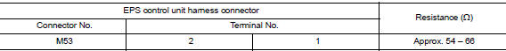
Is the measurement value within the specification?
YES >> GO TO 3.
NO >> Repair the EPS control unit branch line.
3.CHECK POWER SUPPLY AND GROUND CIRCUIT
Check the power supply and the ground circuit of the EPS control unit. Refer to STC "Diagnosis Procedure".
Is the inspection result normal?
YES (Present error)>>Replace the EPS control unit. Refer to STC "Removal and Installation".
YES (Past error)>>Error was detected in the EPS control unit branch line.
NO >> Repair the power supply and the ground circuit.
 DLC Branch line circuit
Diagnosis Procedure 1.CHECK CONNECTOR 1. Turn the ignition switch OFF. 2. Disconnect the battery cable from the negative terminal. 3. Check the terminals and connectors of the data link connecto ...
M&A Branch line circuit
Diagnosis Procedure 1.CHECK CONNECTOR 1. Turn the ignition switch OFF. 2. Disconnect the battery cable from the negative terminal. 3. Check the terminals and connectors of the combination meter ...
Other materials:
Differential side oil seal
Exploded View
1. Transaxle assembly 2. Differential side oil seal (left side) 3.
Differential side oil seal (right side)
Front Genuine
NISSAN Matic S ATF
Removal and Installation
NOTE:
When removing components such as hoses, tubes/lines, etc., cap or plug openings
to prevent fluid fr ...
Low tire pressure warning lamp
Component Function Check
1.CHECK THE ILLUMINATION OF THE LOW TIRE PRESSURE WARNING LAMP
Check that the low tire pressure warning lamp is turned OFF after
illuminating for approximately 1 second,
when the ignition switch is turned ON.
Is the inspection result normal?
YES >> Inspection En ...
Categories
- Manuals Home
- Nissan Versa Owners Manual
- Nissan Versa Service Manual
- Video Guides
- Questions & Answers
- External Resources
- Latest Updates
- Most Popular
- Sitemap
- Search the site
- Privacy Policy
- Contact Us

0.0048