Nissan Versa (N17): M&A Branch line circuit
Diagnosis Procedure
1.CHECK CONNECTOR
1. Turn the ignition switch OFF.
2. Disconnect the battery cable from the negative terminal.
3. Check the terminals and connectors of the combination meter for damage, bend and loose connection (unit side and connector side).
Is the inspection result normal?
YES >> GO TO 2.
NO >> Repair the terminal and connector.
2.CHECK HARNESS FOR OPEN CIRCUIT
1. Disconnect the connector of combination meter.
2. Check the resistance between the combination meter harness connector terminals.
NOTE: Check the vehicle type confirm the service information. Refer to MWI "Information".
- Models with Type A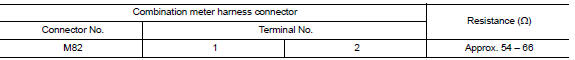
- Models with Type B 
Is the measurement value within the specification?
YES >> GO TO 3.
NO >> Repair the combination meter branch line.
3.CHECK POWER SUPPLY AND GROUND CIRCUIT
Check the power supply and the ground circuit of the combination meter. Refer to the following.
- TYPE A: MWI "COMBINATION METER : Diagnosis Procedure"
- TYPE B: MWI "COMBINATION METER : Diagnosis Procedure"
Is the inspection result normal?
YES (Present error)>>Replace the combination meter. Refer to the following.
- TYPE A: MWI "Removal and Installation"
- TYPE B: MWI"Removal and Installation"
YES (Past error)>>Error was detected in the combination meter branch line.
NO >> Repair the power supply and the ground circuit.
 EPS Branch line circuit
Diagnosis Procedure 1.CHECK CONNECTOR 1. Turn the ignition switch OFF. 2. Disconnect the battery cable from the negative terminal. 3. Check the terminals and connectors of the EPS control unit f ...
STRG Branch line circuit
Diagnosis Procedure 1.CHECK CONNECTOR 1. Turn the ignition switch OFF. 2. Disconnect the battery cable from the negative terminal. 3. Check the terminals and connectors of the steering angle senso ...
Other materials:
Engine stand setting
Setting
NOTE:
The following procedures explain how to disassemble the engine with the engine
stand fastened to the bell
housing. Some steps may be different if using a different type of engine stand.
1. Install engine to engine stand:
a. Rem ...
P074C Unable to engage 4GR
Description
This malfunction is detected when the A/T does not shift into 4GR position as
instructed by TCM. This is not
only caused by electrical malfunction (circuits open or shorted) but by
mechanical malfunction such as control
valve sticking, improper solenoid valve operation, etc.
DTC ...
Categories
- Manuals Home
- Nissan Versa Owners Manual
- Nissan Versa Service Manual
- Video Guides
- Questions & Answers
- External Resources
- Latest Updates
- Most Popular
- Sitemap
- Search the site
- Privacy Policy
- Contact Us

0.0049